Bosch VG4-A-PSU1 Power Supply Unit for CCTV Cameras User Manual
Page 26
26
en | Video and Control Cables (AUTODOME VG5-600 Camera Models ONLY)
Power Supply Units (AUTODOME7000, MIC7000
cameras)
2020-10 | |
Installation Manual
Bosch Security Systems, Inc.
RS-485 is capable of controlling a true multi-drop network and is specified for up to 32 drivers
and 32 receivers on a single 2-wire bus. The AUTODOME camera uses the 2-wire mode,
although RS-485 can be connected in a 2- or 4-wire mode.
Notice!
The wire shield must be tied to signal at both ends, if 2-wire twisted pair is used. After
connecting the wires for RS-485 operation, make sure the slide switch on the main board to
the camera head is positioned toward the LEDs (default).
!
Caution!
Bosch recommends that multiple RS-485 connections be arranged as a connected series of
point-to-point (multi-dropped) nodes, as a line or as a bus. It is
not
recommended to arrange
RS-485 connections as a star, ring, or as a multiple-connected network. Star and ring
topologies may cause signal reflections or excessively low or high termination impedance.
Wire Type
2-wire shielded twisted pair
Distance
1219 m (4000 ft)
Maximum Baud Rate
57.6 kb
Gage
0.511 mm (24 AWG)
Wire Impedance
120 W
Slide Switch
Toward LEDs (factory default)
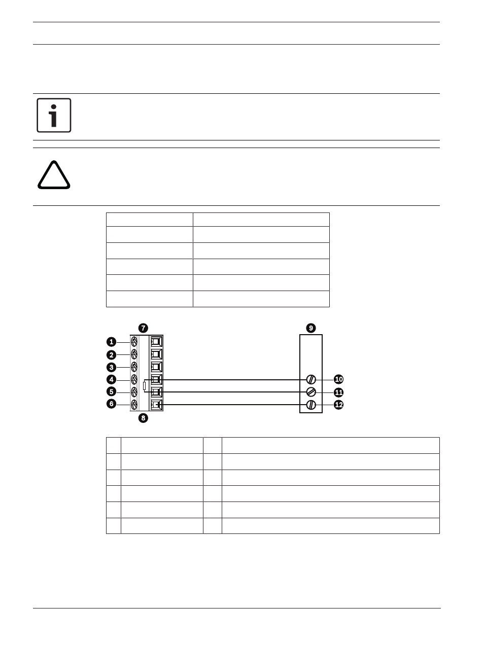
The following figure illustrates the connections for RS-485 connections.
100
Ω
Figure 9.5:
Connections for RS485 Operations
1
C- (Biphase)
7
AUTODOME Data In/Out
2
C+ (Biphase)
8
P105/P106 Connector in Power Supply Box
3
Earth Ground
9
Head End RS-485
4
RxD
10
Data +
5
TxD
11
Data -
6
Signal Ground
12
Ground