Bosch VG4-A-PSU1 Power Supply Unit for CCTV Cameras User Manual
Page 16
16
en | Route Wires and Attach Connectors
Power Supply Units (AUTODOME7000, MIC7000
cameras)
2020-10 | |
Installation Manual
Bosch Security Systems, Inc.
4
Transformer
9
Earth-grounded conduit with power input
and earth-ground connection
5
Ethernet Wire
10
Earth-grounded conduit with Ethernet
video/control, audio input and output to
“head-end“ system
11
Earth-grounded conduit to camera
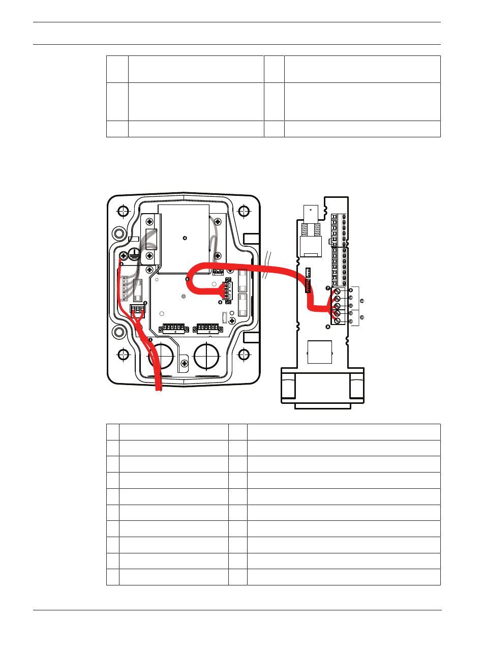
Method Two is to bypass the Power Supply Box and route the video, control, and alarm wires
directly to the Interface Board. You connect only the power wires inside the Power Supply
Box. All conduit and junction boxes used must be electrically earth-grounded.
GND TXD
RXD
C+
C-
GND TXD
RXD
C+
C-
P101
P106
P105
P1
0
7
XF
1
02
XF
1
0
3
XF
1
0
1
5
4
3
2
1
J1
03
J1
03
J1
03
J102
J101
(LED)
HTR DOME
(FUSE)
(FUSE)
(FUSE)
(FUSE)
BNC
J102
P10
7
P101
P102
P103
P104
P106
J101
AGND
A7
A6
A5
A4
A3
AGND
OUT 3
OUT 2
OUT 1
P105
LINE NC NEUT
Figure 7.2:
VG4-A-PSU1 or VG4-A-PSU2 Power Supply Box Connected to Pipe Interface Board
VG4-A-PSU1/VG4-A-PSU2
Pipe Interface Board
1
120 VAC/230 VAC Power In
7
P101 Connector
2
P101 Connector
8
P107 Connector
3
Ground Connection
9
24 VAC Power In (to camera)
4
Transformer
10
Earth Ground
5
24 VAC Power Out
11
24 VAC Power In (to camera)
6
P107 Connector
12
24 VAC Power In (to Heater)
13
24 VAC Power In (to Heater)
14
Camera Power
15
Heater Power