Installation and operation, cont’d, J10 j8 j9, Rgb 400 series installation and operation – Extron Electronics RGB 400 Series User Manual
Page 9
RGB 400 Series Installation and Operation
RGB 400 Series Installation and Operation
Installation and Operation, cont’d
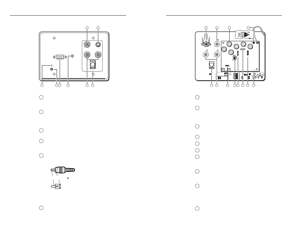
7
J13 jumper
—
Pin 1 = +5V, pin 2 = -5V, pin 3 = ground.
8
SW1 DIP switches
—
1. ON = Removes serration pulses.
2. ON = Enables Digital Display Sync Processing
(DDSP).
9
J10 blue gain/peaking jumper
— Settings are shown
on the label located below the circuit board.
10
J9 green gain/peaking jumper
11
J8 red gain/peaking jumper
12
Circuit board
— Only key components are shown here.
13
Composite video pass-through RCA connector
— If
you remove this connector, replace it with the 0.31”
diam. plastic plug that is shipped with the RGB 402.
14
S-video pass-through 4-pin mini DIN connector
— If
you remove this connector, replace it with the 0.50”
diam. plastic plug that is supplied with the RGB 402.
15
BNC output connectors
— These 6 connectors are for
video and sync output. Connect the coax cables’ BNC
connectors as shown on page 2-6 for red, green and
blue video output, and either separate horizontal and
vertical sync or composite sync.
16
Twisted pair wires
— Splice these wires to a
12 to 24VAC or VDC power source.
J10
J9
J8
RGB 406/
RGB 408
Captive
Screw
Connector
J13
33-398-01 B 08 99
J10
J8
J9
J10
J8
J9
ON
1 = +5V 20 mA max.
2 = –5V 20 mA max.
3 = Ground
SW1
3 2 1
1. ON = Remove
serration pulses.
2. ON = Digital
display sync.
.8V
.9V
.7V
.7V
.7V
.8V .9V
V
H
CS
B
G
R
Black
Red
Yellow
Green
5
6
13
14
15
REAR
7
8
9
11
12
16
10
2-9
1
Auto power LED
— If active sync pulses are present,
power and this LED turn on. If not, power and this
LED turn off.
2
H. Shift (horizontal shift) control
— This controls
the horizontal centering. If output is SOG, or if DIP
SW1-2 (DDSP) is set to On, the horizontal shift
control is disabled.
3
Input
— This 9-pin D-sub male connector is for RGB
analog input.
4
High Z/75 Ohm switch
— For proper video
termination, set this switch to 75 Ohms if no local
monitor will be connected.
5
Left and right audio channel pass-through RCA
connectors
— The input to the RCA connectors
should be wired as shown here.
Tip
Sleeve ( )
If you remove these connectors, replace them with
the 0.31 inch diameter plastic plugs supplied with the
RGB 402.
6
Network pass-through RJ-45 connector
RGB 402 front and rear features
VIDEO
S-VIDEO
AUDIO
NETWORK
L
R
Extron
RGB 402
INPUT
HIGH Z
75 Ohm
H. SHIFT
AUTO POWER
5
6
13
14
1
2
3
FRONT
4
2-8