Installation and operation, cont’d, Cabling and connections – Extron Electronics RGB 400 Series User Manual
Page 13
RGB 400 Series Installation and Operation
RGB 400 Series Installation and Operation
Installation and Operation, cont’d
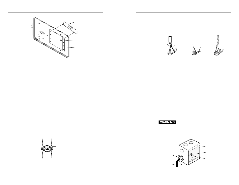
Cabling RCA connectors
For composite video, solder the center conductor of a
coaxial cable to the central solder cup of the RCA connector.
Solder the cable’s shield to the grounded grounding tab.
See the leftmost and center illustrations below.
Attaching coaxial and twisted-pair cables to
RCA connectors
For audio, solder the signal wire of a shielded twisted-pair
cable to the central solder cup of the RCA connector. Solder
the ground wire to the grounded tab, as shown above at right.
Connecting shields
Multiconductor cables such as Extron’s Install Plenum bulk
cable contain several braided and foil shields. At the
interface end of the cable, the outer braided and foil
shields
should be connected to the grounded metal wall
box (or to a grounding wire if a metal wall box is not used).
The wires that make up the braided shield can be
unbraided, then twisted together to form a large, multi-
strand wire that can be folded back under the wall box
cable clamp or attached to the metal wall box with a screw.
See the illustration below.
To prevent short circuits, the outer foil shield
can be cut back to the point where the cable
exits the cable clamp. Both the braided and foil
shields should be connected to an equipment
ground at the other end of the cable.
Grounding outer braided and foil shields
Shield
Center
Conductor
RCA Connector
Coaxial Cable
Twisted Pair
Central Solder
Cup
Grounding Tab
Metal Wall Box
Screw
Braided Shield
Install Cable
Foil Shield
Cable Clamp
2-17
#4-40 Nut w/Captive
Washer
RGB 408 (Up to 4 Plates)
Adapter Plate
INP
UT
AUTO POWER
75 O
hm
H. S
HIF
T
HIG
H Z
AUDIO
RGB 408
Installing optional adapter plates
Cabling and connections
Attaching cables to pass-through connectors
The RGB 402 and RGB 404 provide pass-through connectors
for composite video, S-video, RJ-45 network and, for the
RGB 402 only, two-channel stereo audio. These connectors
are mounted on the faceplate. The RJ-45 cable can be
plugged in from the back. Coaxial cables and/or twisted
pair wires must be soldered to the back side of the S-video
and RCA connectors, as described in this section.
Optional adapter plates with various types and
combinations of pass-through audio and video connectors
are available for the RGB 408. Many adapter plates also
require cables and wires to be soldered to the rear
connectors.
Cabling S-video connectors
The illustration below identifies the S-video connector
signal leads. For the RGB 402/404, splice and solder the
four wires from this
connector to user-supplied
coaxial cables. Insulate the
soldered connections to
prevent shorts. You can
also use the connector’s
shield tabs for
chrominance and
luminance ground tie
points.
S-video connector wiring diagram
Chrominance
signal
Luminance
signal
Chrominance
ground
Luminance
ground
Red
Y
e
llo
w
Green
Blac
k
Shield tab
2-16