Installation and operation, cont’d, Pre-installation testing/troubleshooting – Extron Electronics RGB 400 Series User Manual
Page 15
RGB 400 Series Installation and Operation
RGB 400 Series Installation and Operation
Installation and Operation, cont’d
Pre-installation testing/troubleshooting
Before installing the interface into the wall or furniture, test
the system to make sure that the connections and interface
settings are correct.
Turn on the input device(s) (computer, audio device) and
output device(s) (projector and/or monitor, speakers). The
image should now appear on the screen, and, for all models
except the RGB 400, sound should be audible.
If the image does not appear or there is no sound
1.
Ensure that all devices are plugged in.
2.
Make sure that each device is receiving power. The
interface’s Auto power indicator LED will light if the
interface is receiving power and an active sync signal.
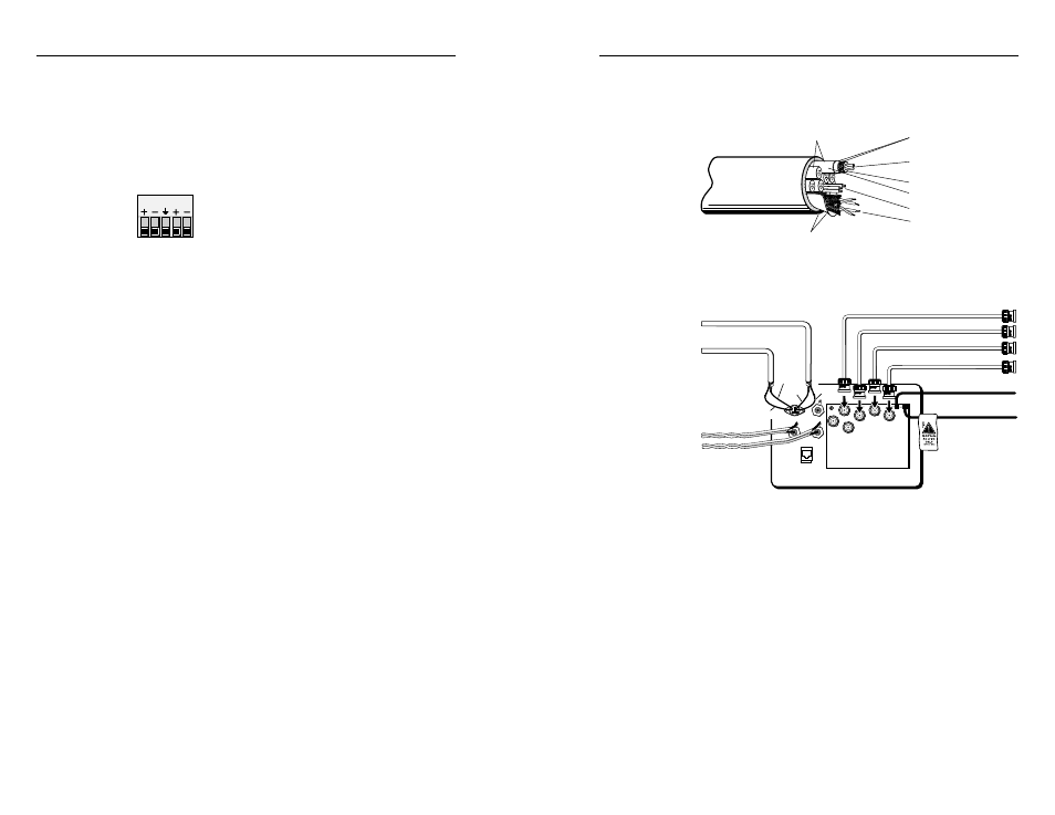
Using installation cable
Extron’s Install Plenum bulk cable (shown here) is ideal for
mountable interfaces such as the RGB 400 Series models.
Double Shielded
Foil and Copper Strand
Center Conductor
(Stranded)
Sheath
Plenum Jacket, Double Shielded
Foil and Copper Strand
Polyethylene Foam
Four Sets of Twisted Pair
(Stranded), Wire Braid Shield
Six Mini, High-resolution
Coaxial Conductors
17-Conductor Install Plenum Cable
Three 20-gauge Wires
Below is an example of how the cable can be used.
Red & Black
Twisted Pair
White & Black
Twisted Pair
20 Gauge Violet
Yellow Mini-Coax
White Mini-Coax
20 Gauge Gray
Red
Yellow
Green
Red
Black
RGB 402 Rear
Black Mini-Coax
Blue Mini-Coax
Green Mini-Coax
Red Mini-Coax
Shield to Black
Shield to Green
Using installation cable with an RGB 402
2-21
output captive screw connector. See “Connecting
shields” earlier in this chapter for details.
Connecting audio cables — RGB 406, RGB 408
Each RGB 406 or RGB 408 accepts an unbalanced audio
input from a front panel 3.5 mm PC-type stereo connector,
and it outputs two channels of balanced audio on a 3.5 mm,
5-pole captive screw connector on the rear of the circuit
board. Follow the steps listed for the RGB 404
for inserting wires into captive screw
connectors. Use the label on the rear of the
faceplate (excerpted here) as a wiring guide.
Connecting input cables and video output cables
With appropriate cables, connect the computer and, for all
models except the RGB 400, audio device(s) to the interface
via the front panel input connectors. Connect all the
devices for pass-through input (network, composite video,
S-video and/or other inputs) via front panel or front
adapter plate connectors.
Determine what computer-video format the display device
requires: separate horizontal and vertical sync (RGBHV),
composite sync (RGBS), or sync on green (RGsB or SOG).
No matter what format the computer outputs to the
interface, the output from the interface to the display device
can be RGBHV or RGBS. If the video format input to the
interface is RGsB (SOG), RGsB can be output to the display
device; otherwise only RGBHV and RGBS are available as
output options.
Connect the display device to the interface using coaxial
cables. Attach the cable’s BNC connectors to the
appropriate rear panel BNC connectors on the interface
based on the video format required by the display device.
Attaching power cables
Each RGB 400 Series interface requires an external voltage
source of 12 to 24 volts AC or DC (250 mA maximum, 5 W).
The interfaces are supplied with a power cord of twisted-
pair wire soldered to the circuit board.
1.
Splice these wires to the cord of a user-supplied
power source. Polarity is not important, even if the
power source supplies DC voltage. Extron offers an
optional external power supply. See Appendix D for
the part number.
2.
Solder and insulate the connections.
1 2 3 4 5
2-20