Slave driver – ProSoft Technology MVI71-MCM User Manual
Page 76
MVI71-MCM ♦ PLC Platform
Reference
Modbus Communication Module
Page 76 of 111
ProSoft Technology, Inc.
December 28, 2007
The control register is cleared (a value of 0) after the operation is executed with
the exception of the 9997 command. If the module fails to successfully transfer
the configuration to the processor, an error code will be returned in the control
register as follows:
Code Description
0
No error, transfer successful
-1
Error transferring general configuration information.
-2
Error transferring Modbus Port 1 master command list
-3
Error transferring Modbus Port 2 master command list
Ladder logic must handle the 9997 command. No ladder logic is required when
using the warm or cold boot commands.
5.2.12 Data Flow Between MVI71-MCM Module and PLC Processor
The following topics describe the flow of data between the two pieces of
hardware (PLC processor and MVI71-MCM module) and other nodes on the
Modbus network under the module's different operating modes. Each port on the
module is configured to emulate a Modbus master device or a Modbus slave
device. The operation of each port is dependent on this configuration. The
sections below discuss the operation of each mode.
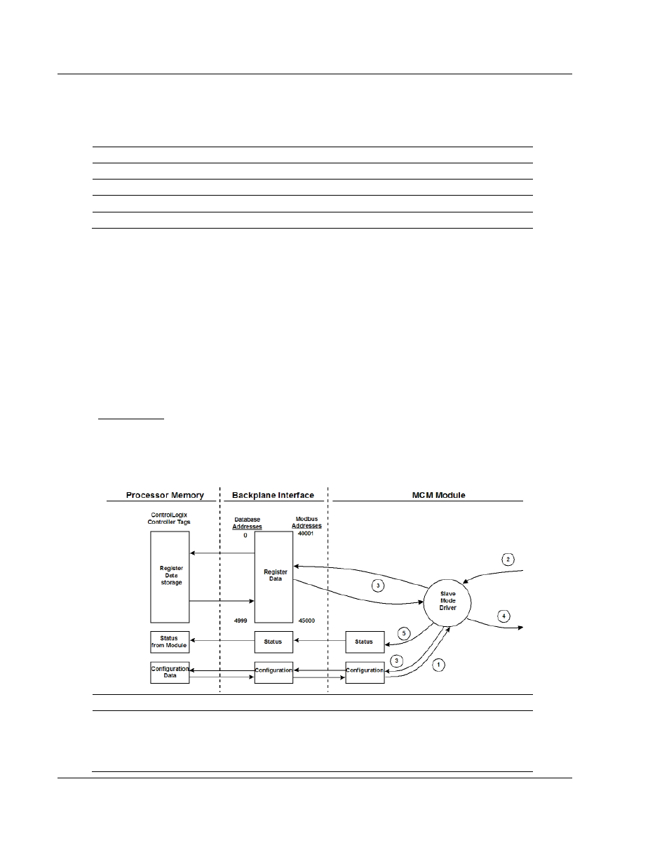
Slave Driver
The Slave Driver Mode allows the MVI71-MCM module to respond to data read
and write commands issued by a master on the Modbus network. The following
flow chart and associated table describe the flow of data into and out of the
module.
Step Description
1
The Modbus slave port driver receives the configuration information from the PLC
processor. This information configures the serial port and define the slave node
characteristics. Additionally, the configuration information contains data that can be
used to offset data in the database to addresses requested in messages received from
master units.