Configuration data transfer, Module configuration – ProSoft Technology MVI71-MCM User Manual
Page 23
Installing and Configuring the Module
MVI71-MCM ♦ PLC Platform
Modbus Communication Module
ProSoft Technology, Inc.
Page 23 of 111
December 28, 2007
2.2.2 Configuration Data Transfer
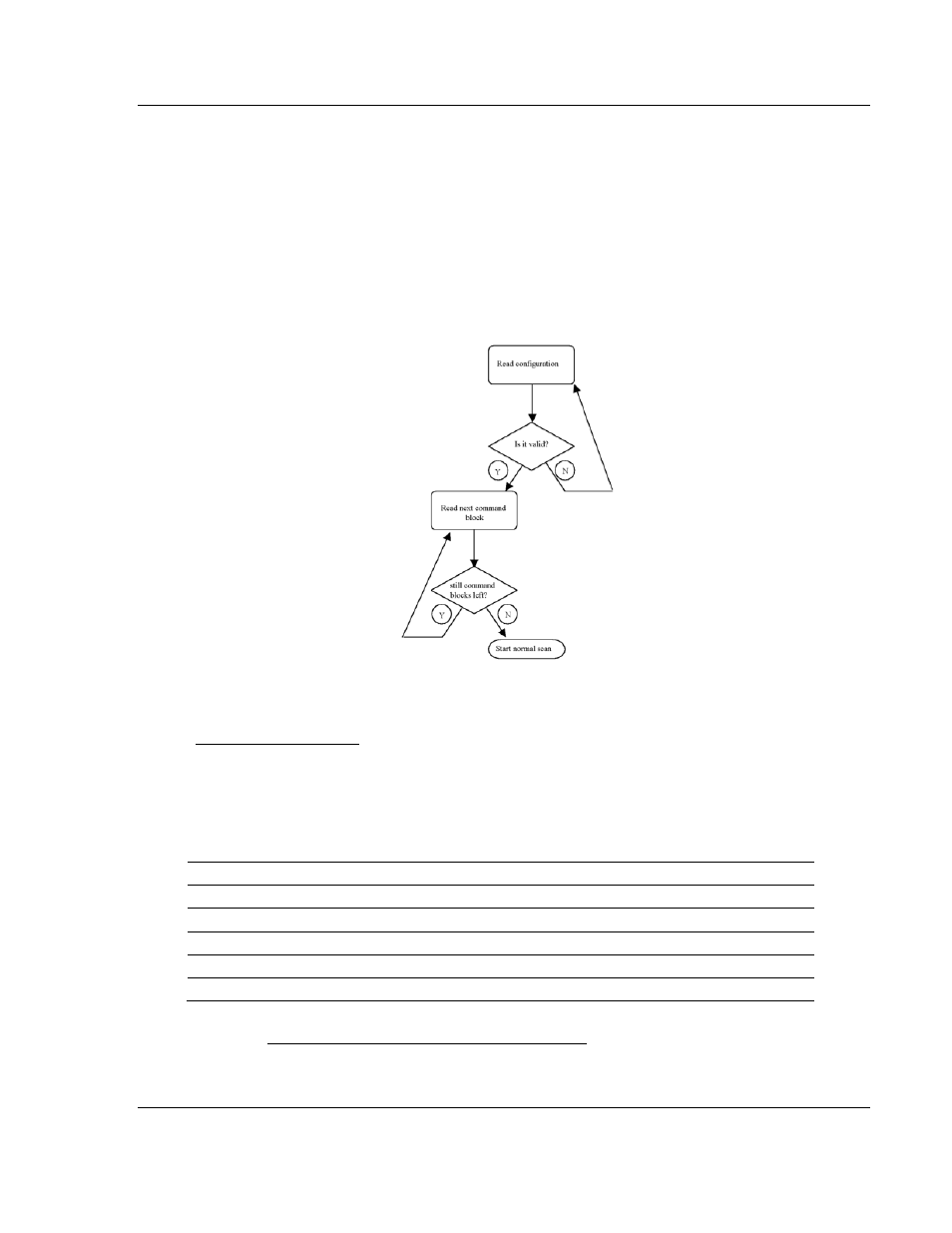
When the module performs a restart operation, it will request configuration
information from the PLC processor. This data is transferred to the module in
specially formatted write blocks (output image). The module will poll for each
block by setting the required write block number in a read block (input image).
Refer to the Configuring the Module section for a description of the data
objects used with the blocks and the ladder logic required. The module will
request all command blocks, according to the number of commands configured
by the user for each Master port. The following illustration shows this procedure:
The format of the blocks for configuration is given in the following topics.
Module Configuration
This block sends general configuration information from the processor to the
module. The data is transferred in a block with an identification code of 9000.
The structure of the block is displayed in the following table:
Write Block
Offset Description
Length
0 9000
1
1 to 6
Backplane Setup
6
7 to 31
Port 1 Configuration
25
32 to 56
Port 2 Configuration
25
57 to 63
Spare
7
The read block used to request the configuration has the following structure
(Refer to MVI71-MCM Configuration Data Definition (page 87) for a listing of
configuration data):