Normal data transfer, Read block – ProSoft Technology MVI71-MCM User Manual
Page 63
Reference MVI71-MCM
♦ PLC Platform
Modbus Communication Module
ProSoft Technology, Inc.
Page 63 of 111
December 28, 2007
Ex. 2
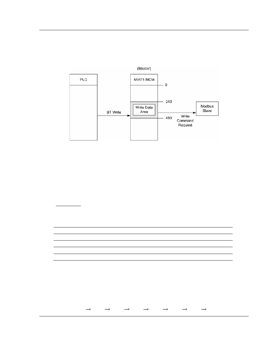
: The next figure shows another example of how to use the Write Data Area;
an MVI71-MCM port configured as a Master sends a Modbus Write Command to
a slave device. The Modbus Write Command source address in the MVI71-MCM
database must be located inside the Write Data Area (between addresses 240
and 479).
5.2.7 Normal Data Transfer
Normal data transfer includes the paging of the user data found in the module's
internal database in registers 0 to 4999 and the status data. These data are
transferred through read (input image) and write (output image) blocks. Refer to
the Module Set Up section for a description of the data objects used with the
blocks and the ladder logic required. The structure and function of each block is
discussed below.
Read Block
These blocks of data transfer information from the module to the PLC processor.
The structure of the input image used to transfer this data is shown in the
following table:
Offset Description
Length
0
Read Block ID
1
1
Write Block ID
1
2 to 61
Read Data
60
62 to 63
Spare
2
The Read Block ID is an index value used to determine the location of where the
data will be placed in the PLC processor user data table. Each transfer can move
up to 60 words (block offsets 2 to 61) of data.
The Write Block ID associated with the block requests data from the PLC
processor. Under normal, program operation, the module sequentially sends
read blocks and requests write blocks. For example, if three read and two write
blocks are used with the application, the sequence will be as follows:
R1W1
R2W2
R3W1
R1W2
R2W1
R3W2
R1W1