Read data area application examples – ProSoft Technology MVI71-MCM User Manual
Page 61
Reference MVI71-MCM
♦ PLC Platform
Modbus Communication Module
ProSoft Technology, Inc.
Page 61 of 111
December 28, 2007
The configuration first creates four possible blocks for each Read and Write area
since every block contains 60 registers. Therefore, the Read and Write Block ID
generated would be:
Read Block ID
Write Block ID
0 3
1 4
2 1
3 2
4 3
-1 4
0 1
1 2
2 3
If the ladder logic takes too much time to send a BTW instruction, the module
sends a new BTR instruction requesting the same Write Block ID.
The Read Block ID 0 is a null block to guarantee ladder logic consistency if the
user sets an empty Read Data area. The Read Block ID -1 transfers the
configuration data.
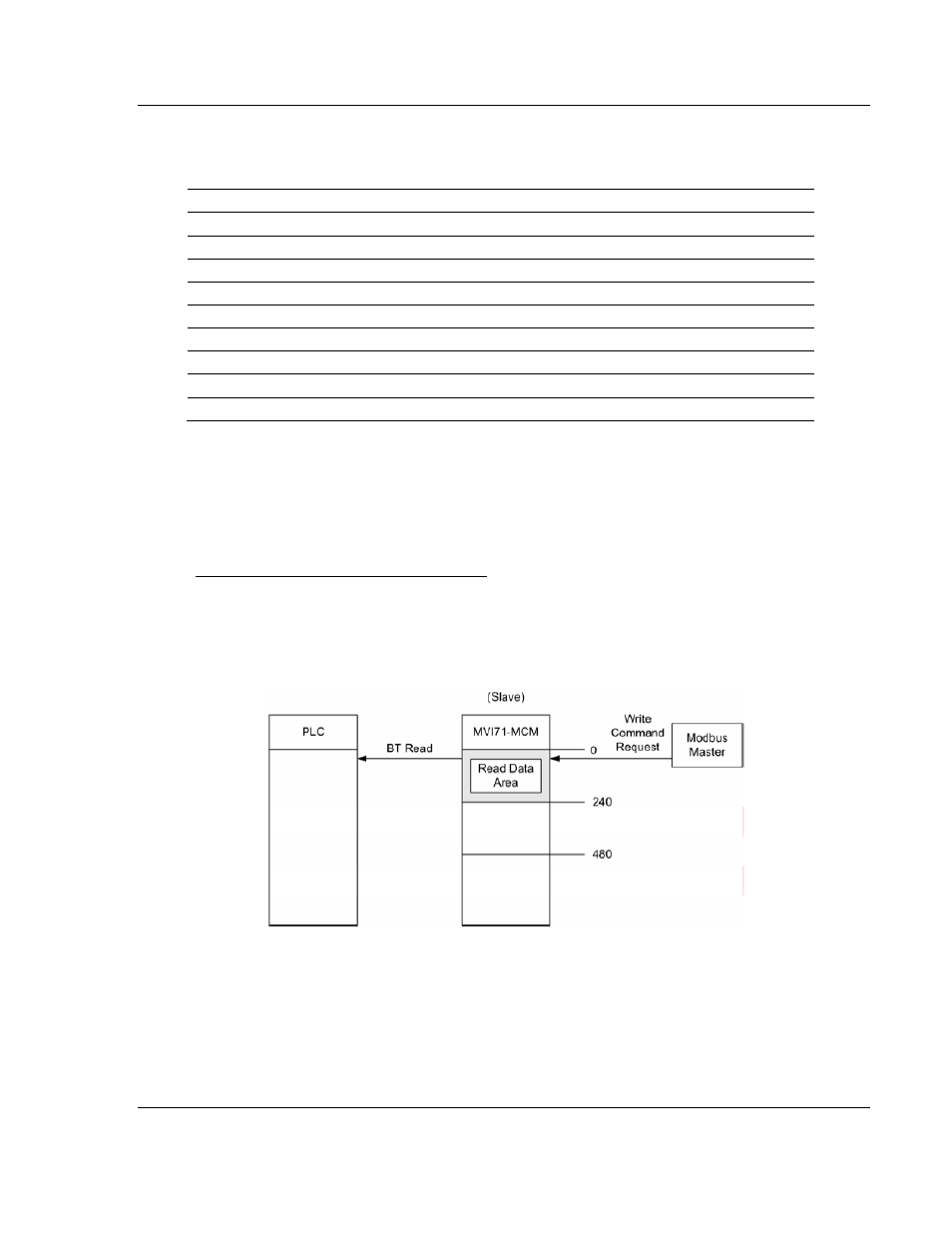
Read Data Area Application Examples
Ex. 1
: The following example shows a Read Data Area application; A Modbus
Master device sends a Modbus Write Command to an MVI71-MCM slave port.
The command destination address must be located inside the Read Data Region
(between 0 and 239).
- ILX69-PBS (102 pages)
- MVI69E-LDM (130 pages)
- ILX69-PBM (124 pages)
- MVI69L-MBTCP (152 pages)
- PS69-DPS (108 pages)
- MVI69E-MBTCP (150 pages)
- MVI69L-MBS (154 pages)
- MVI69E-MBS (162 pages)
- PS69-DPM (130 pages)
- MVI69-FLN (137 pages)
- MVI69-DFNT (167 pages)
- MVI69-GEC (86 pages)
- MVI69-PDPS (96 pages)
- MVI46-S3964R (80 pages)
- MVI46-S3964R (78 pages)
- MVI46-DNPSNET (119 pages)
- MVI69-ADMNET (122 pages)
- MVI56-104S (188 pages)
- MVI69-ADM (342 pages)
- MVI69-MCM (167 pages)
- 5307-MBP-HART (169 pages)
- MVI69-PDPMV1 (225 pages)
- MVI69-GSC (102 pages)
- MVI69-DNP (129 pages)
- MVI69-DFCM (117 pages)
- MVI69-103M (131 pages)
- PC56-OPC (34 pages)
- MVI46-MBP (101 pages)
- MVI69-101S (149 pages)
- MVI56-103M (152 pages)
- MVI56-DFCMR (113 pages)
- MVI56-DNP (193 pages)
- MVI56-LTQ (98 pages)
- ILX56-MM (112 pages)
- MVI56-BAS (234 pages)
- MVI56-DFCM (106 pages)
- MVI46-PDPS (88 pages)
- MVI56E-MNETCR (159 pages)
- MVI46-AFC (316 pages)
- MVI56E-MNETC (183 pages)
- MVI56E-GSC/ GSCXT (140 pages)
- MVI56-PDPMV1 (255 pages)
- MVI46-MNETC (153 pages)
- CLX-APACS (53 pages)
- MVI56E-MNET/MNETXT (181 pages)