PLANET GS-4210-8P2T2S User Manual
Page 124
User’s Manual of GS-4210-8P2T2S
1.
While
[PC-1] transmits an untagged packet enters Port-1, the Managed Switch will tag it with a VLAN Tag=2.
[PC-2] and [PC-3] will received the packet through Port-2 and Port-3.
2.
[PC-4],[PC-5] and [PC-6] received no packet.
3.
While the packet leaves
Port-2, it will be stripped away its tag becoming an untagged packet.
4.
While the packet leaves
Port-3, it will keep as a tagged packet with VLAN Tag=2.
Tagged packet entering VLAN 2
1.
While
[PC-3] transmits a tagged packet with VLAN Tag=2 enters Port-3, [PC-1] and [PC-2] will receive the packet
through
Port-1 and Port-2.
2.
While the packet leaves
Port-1 and Port-2, it will be stripped away its tag becoming an untagged packet.
Untagged packet entering VLAN 3
1.
While
[PC-4] transmits an untagged packet enters Port-4, the switch will tag it with a VLAN Tag=3. [PC-5] and
[PC-6] will receive the packet through Port-5 and Port-6.
2.
While the packet leaves
Port-5, it will be stripped away its tag becoming an untagged packet.
3.
While the packet leaves
Port-6, it will keep as a tagged packet with VLAN Tag=3.
In this example, VLAN Group 1 is set as default VLAN, but only focuses on VLAN 2 and VLAN 3 traffic
flow.
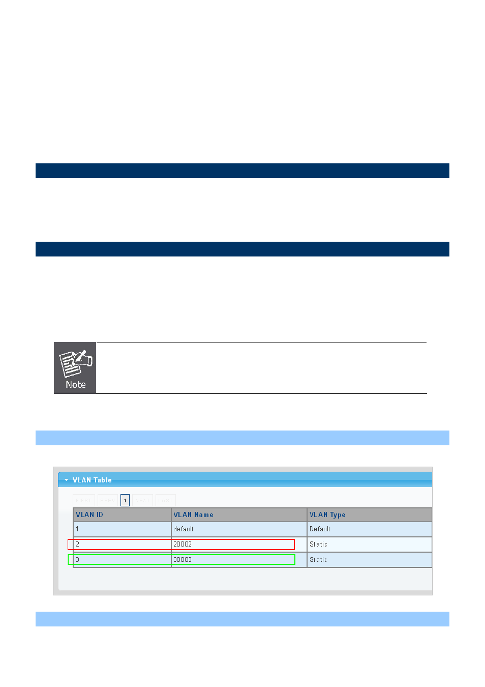
Setup Steps
1. Create VLAN Group 2 and 3
Add VLAN group 2 and group 3
2. Assign VLAN mode and PVID for each port:
124