Amprobe – Amprobe Multitest-2000 Continuity-Tester User Manual
Page 170

AMPROBE
MULTITEST2000
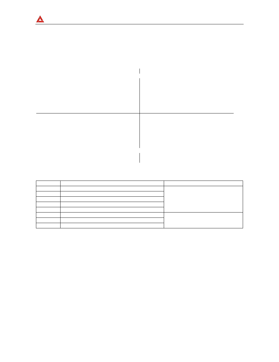
16.7.1. Conventions on powers and power factors
As for the recognition of the type of reactive power, of the type of power factor and of the
direction of the active power, the below conventions must be applied. The stated angles
are those of phase-displacement of the current compared to the voltage (for example, in
the first panel the current is in advance from 0° to 90° compared to the voltage):
Equipment under test = Inductive Generator
Equipment under test = Capacitive Load
90°
180°
P+ = 0
Pfc+ = -1
Pfi+ = -1
Qc+ = 0
Qi+ = 0
P - = P
Pfc - = -1
Pfi - = Pf
Qc- = 0
Qi - = Q
P+ = P
Pfc+ = Pf
Pfi+ = -1
Qc+ = Q
Qi+ = 0
P - = 0
Pfc - = -1
Pfi - = -1
Qc- = 0
Qi - = 0
0°
P+ = 0
Pfc+ = -1
Pfi+ = -1
Qc+ = 0
Qi+ = 0
P - = P
Pfc - = Pf
Pfi - = -1
Qc- = Q
Qi - = 0
P+ = P
Pfc+ = -1
Pfi+ = Pf
Qc+ = 0
Qi+ = Q
P - = 0
Pfc - = -1
Pfi - = -1
Qc- = 0
Qi - = 0
270°
Equipment under test = Capacitive Generator
Equipment under test = Inductive Load
where:
Symbol Significance
Remarks
P+
Value of the active power +
Pfc+
Capacitive power factor +
Pfi+
Inductive power factor +
Qc+
Value of the capacitive reactive power +
Qi+
Value of the inductive reactive power +
Positive parameter
(user)
P-
Value of the active power -
Pfc-
Capacitive power factor -
Pfi-
Inductive power factor -
Negative parameter
(generator)
