2 n.c. alarm line (open on failure), 1 open on failure using internal dip switches, N.c. alarm line (open on failure) -19 – KEPCO RA 19-4B User Manual
Page 29: Open on failure using internal dip switches -19, R. 2.4.4.2)
RA 19-4B 011409
2-19
2.4.4.2
N.C. ALARM LINE (OPEN ON FAILURE)
The N.C and COM line of each HSF supply provide an open contact (open circuit) upon failure.
To configure multiple power supplies so that a failure of any supply produces a failure indication,
it is necessary to connect the N.C. line of one, with the COM line of the next power supply, so
the alarm line is connected in series.
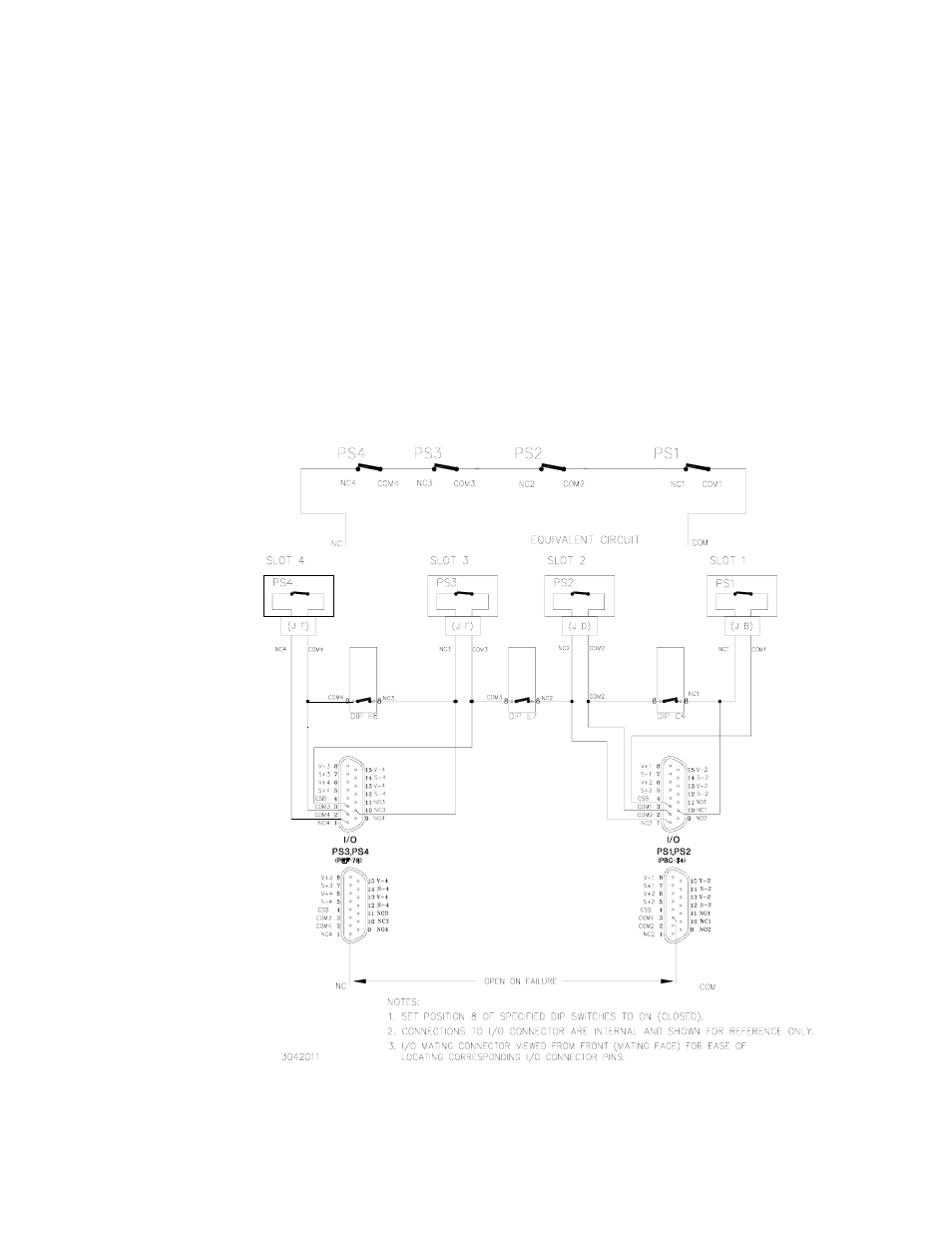
2.4.4.2.1 OPEN ON FAILURE USING INTERNAL DIP SWITCHES
The open on failure alarm for multiple power supplies is accomplished by setting the associated
DIP switch, position 8, to ON (closed) for each slot included in the alarm circuit as indicated in
Figure 2-13. Setting DIP switch position 8 to ON (closed) connects the N.C. line to the COM line
of the adjacent power supply. Figure 2-13 illustrates an open on failure alarm configuration for
four power supplies using internal DIP switch settings.
CAUTION: The user is responsible for ensuring that the alarm circuit does not exceed
DIP switch specifications: 100mA, 50V d-c, maximum.
To configure PS1, PS2 and PS3 as open on failure, set position 8 of DIP switch for slot 2 (C4)
and slot 3 (F8) to ON (closed). The failure indication (open circuit) will be present across N.C.3
and COM 1.
FIGURE 2-13. OPEN ON FAILURE ALARM CONFIGURATION USING INTERNAL DIP
SWITCHES, SIMPLIFIED DIAGRAM