Section 2 - installation, 1 unpacking and inspection, Table 2-1. equipment supplied – KEPCO RA 19-4B User Manual
Page 11: 2 configuring the rack adapter, 3 rack adapter keying instructions, Unpacking and inspection -1, Configuring the rack adapter -1, Rack adapter keying instructions -1, Equipment supplied -1
RA 19-4B 011409
2-1
SECTION 2 - INSTALLATION
2.1
UNPACKING AND INSPECTION
This equipment has been thoroughly inspected and tested prior to packing and is ready for
operation. After careful unpacking, inspect for shipping damage before attempting to operate. If
any indication of damage is found, file an immediate claim with the responsible transport ser-
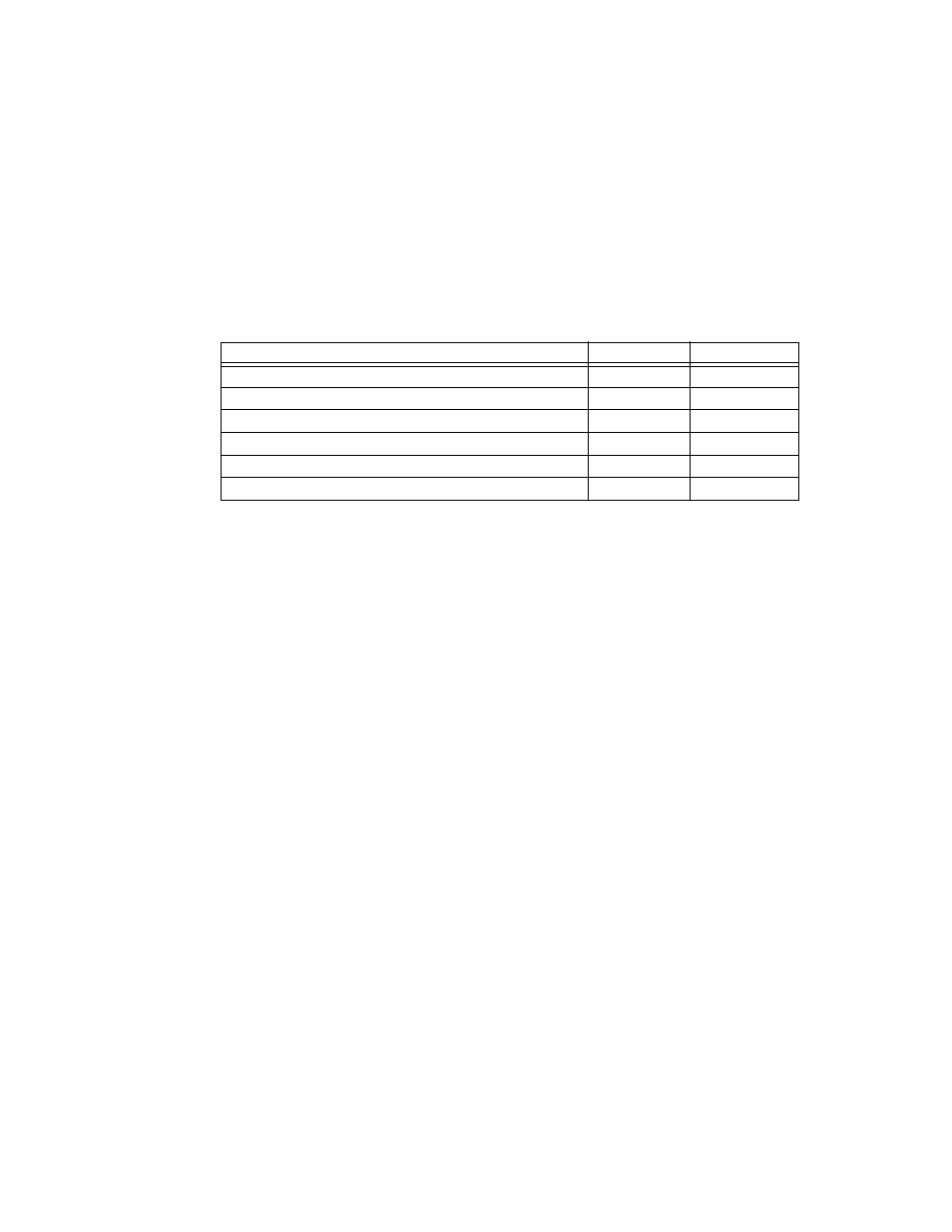
vice. See Table 2-1 for a list of equipment supplied.
2.2
CONFIGURING THE RACK ADAPTER
Prior to installation the rack adapter must be configured by the user. Configuration consists of
the following:
• For configurations that use multiple output voltages it is possible to key the rack adapter
to accept only a power supply with corresponding keying (see PAR 2.3).
• Configuring slots for independent, parallel, or series operation. This can be done by
means of internal DIP switches, or externally by wiring the associated I/O mating con-
nector and DC OUTPUT terminals (see PAR. 2.4).
2.3
RACK ADAPTER KEYING INSTRUCTIONS
Series RA 19-(X)B rack adapters incorporate a keying mechanism to prevent accidental inser-
tion of the incorrect model HSF power supply into any position. The HSF power supplies are
keyed by voltage at the factory. The keying mechanism will prevent engagement of any of the
HSF power supply's connectors with those on the rack adapter's back plate unless the key and
keyway align. The user can configure each power supply position of the rack adapter for the
desired voltage in the desired position (see Figure 2-1). First gain access to the interior compo-
nents (PAR.2.3.1), then position the key as required (PAR. 2.3.2).
NOTE: After removing the rear panel, the keying pins can be accessed through the front of the
rack adapter, although it is recommended that the back plate be removed to gain easy
access to interior components.
2.3.1
DISASSEMBLY TO GAIN ACCESS TO INTERIOR COMPONENTS
NOTE: All power supplies must be removed prior to disassembly.
1. Remove four spacers securing the two I/O connectors to the rear panel
TABLE 2-1. EQUIPMENT SUPPLIED
ITEM
QUANTITY
PART NUMBER
Rack Adapter
1
RA 19-4B
I/O Connector (Mating)
2
142-0449
Line cord (115 V a-c, 15A max, North American style plug, 6 ft.)
2
118-0506
Instruction Manual
1
243-0955
Keying pins
4
108-0305
Hood for I/O Connector (Mating) P/N 142-0449
2
108-0204