Ar. 2.4.2.3.2: pa – KEPCO RA 19-4B User Manual
Page 22
2-12
RA 19-4B 011409
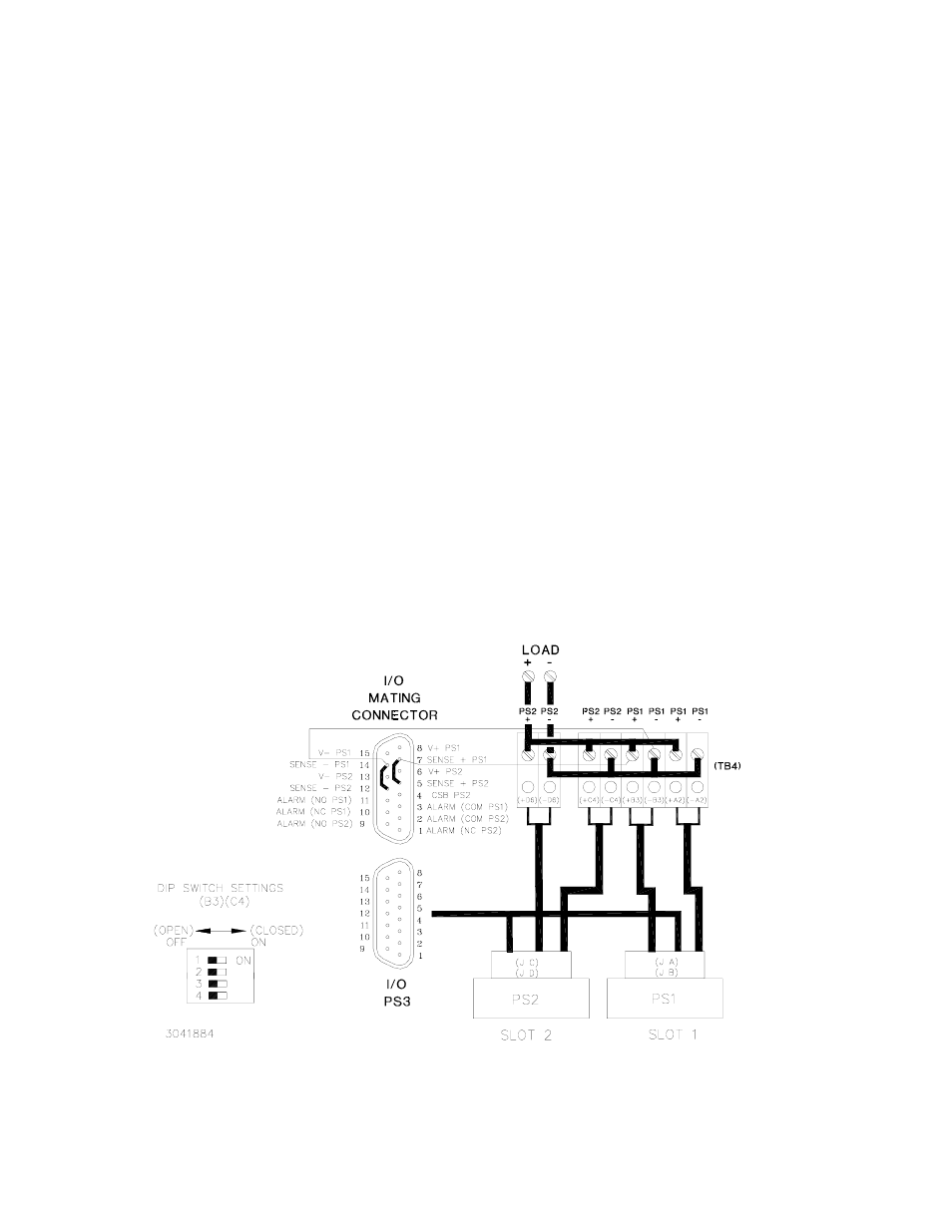
2.4.2.3.2 PARALLEL CONFIGURATIONS USING EXTERNAL WIRES TO CONNECT SENSE LINES
IN PARALLEL AND EXTERNAL WIRES TO CONFIGURE LOCAL SENSING
Figure 2-7 is a simplified diagram of a typical parallel configuration using local sensing via exter-
nal wires to connect V(+) to S(+), V(–) to S(–) and jumpers connected to the I/O mating con-
necter to connect the sense leads in parallel. This configuration requires the following:
1. For each supply in parallel set DIP switch positions 1 and 2 to OFF (open) (see Figure 2-1).
2. For each DIP switch between parallel-connected slots (C4 and F8), set DIP switch positions
3 and 4 to OFF (open) (sense leads will be connected in parallel in steps 7 and 8) (see Fig-
ure 2-1).
3. For each DIP switch between parallel-connected slots configure position 5 to connect the
current share bus by referring to PAR. 2.4.2.2.
4. Configure Positions 6, 7, and 8 (alarms) of each DIP switch per PAR. 2.4.4.
5. Connect wire between I/O mating connector pin Sense (+) and corresponding power supply
V (+) terminal at DC OUTPUT terminal block.
6. Connect wire between I/O mating connector pin Sense (–) and corresponding power supply
V (–) terminal at DC OUTPUT terminal block.
7. Connect short jumper across I/O mating connector Sense (+) pins.
8. Connect short jumper across I/O mating connector Sense (–) pins.
FIGURE 2-7. TYPICAL PARALLEL CONNECTIONS USING EXTERNAL WIRES FOR LOCAL SENSING
AND I/O MATING CONNECTOR JUMPERS TO PARALLEL SENSE WIRES