Chapter 8 analog i/o – Remote Processing RPC-2350 User Manual
Page 43
CHAPTER 8
ANALOG I/O
8-1
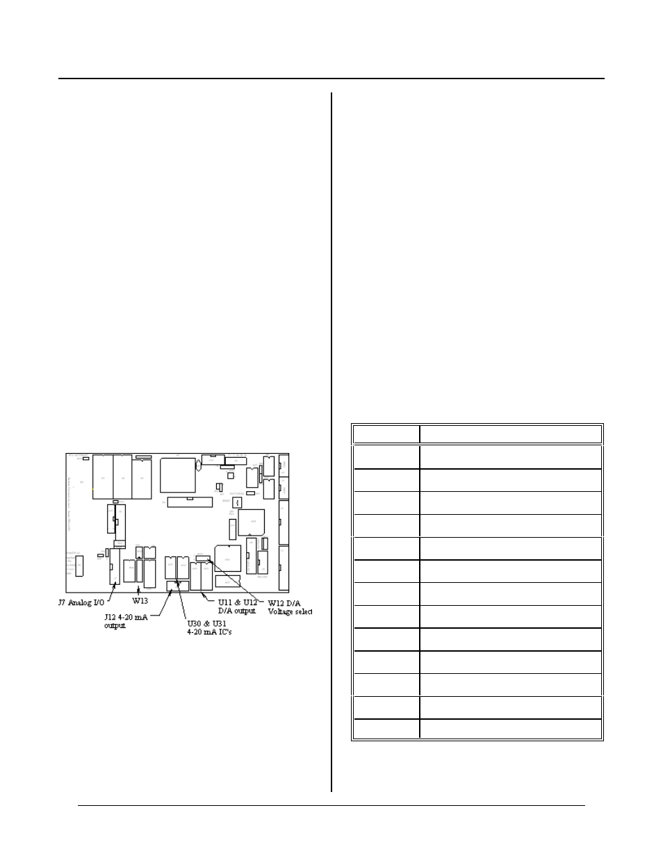
Figure 8-1 Analog connectors and jumpers
CHAPTER SYNOPSIS
Brief description of analog input capabilities
Acquir ing analog da ta
High voltage interfacing
Conve rting analo g reading s to real w orld units
Calibration
Analog output discussion
4-20 mA output
Analog po wer su pply
DESCRIPTION
ANALOG I/O CH APTER 8
The RPC-2350 has eight single ended or four differential
analog input channels than can be interfaced to external
analog devices. These channels can be used to measure
voltages from tr ansducers, 4-20 mA. current loops,
thermistors, etc. The conver ter reads a voltage and
retur ns a 12 bit (4096 count) num ber in und er a m illi-
second. Inputs are progr ammable for 0 to + 5 or ±2.5
volt, single ended or differential mode.
Additionally, 2 analog outpu t channels w ith 12 bit
accuracy are optionally available. Output voltage is 0-
5V, 0-10V , or ±5V. Outputs can drive optional 4-20
mA. current loops.
Filter capacitors may be added to pads designated as
W13. T his can reduce noise on analog inputs. Values
are app lication depend ent. 0.01 mfd is a goo d value to
start fro m. Higher values ma y be used in ex trem ely
noisy envir onmen ts or wh en time be tween sam ples is
long (> 100 ms).
Input impedance is 100K ohm to ground. Inputs are
protected to ±12V. Readings on other channels are
affected when one channel is over range.
Conve rsion tim e is under 500 micr o-seconds/ channel.
AIN function is used to return a voltage while AOT
writes an output voltage.
This chapter begins with basic hook-up information, then
proceeds to initialization, data reading, and calibration.
Analog output option is discussed near the end.
Analog output 1 (AOT 1) may optionally provide
software contrast control for the LCD graphics display.
When it is used for this purpose, 4-20 Ma output or
other voltage output may not be used.
CONNECTING ANALOG I/O
Analog I/O interface via J7. The STB-20 terminal board
may be used to br ing signals to terminal blocks.
The following table defines the signal pin out from
analog I/O port J7.
J7 Pin #
Signal
1
CH0 input
2-16
Ground (e ven pins)
3
CH1 input
5
CH2 input
7
CH3 input
9
CH4 input
11
CH5 input
13
CH6 input
15
CH7 input
17
DAC 0 output
18
+ 12V
19
DAC 1 output (also gr aphics contr ast)
20
-12V