Terminal block layout – RISCO Group SEISMIC Detector RK66S User Manual
Page 7
Seismic Detector
7
EN
iv.
Fit the detector using the supplied fixing screws, see
Figure 2(C).
•
Connect wiring; Refer to Terminal Blocks section.
•
Set Jumpers; Refer to Jumper Selection section.
•
Set Dipswitches; Refer to Dipswitch Settings section.
•
To verify detector operation, perform:
a.
A self test (See Testing the Detector section).
b.
Sensitivity calibration using an external test generator (See
External Test Generator section).
•
Replace the cover and tighten the cover fixing screws; See Figure 1(A) / 2(B).
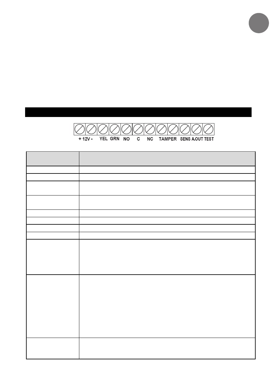
TERMINAL BLOCK LAYOUT
Figure 3: Terminal Block Layout
Terminal
Block
Description
+12V (RED)
Power supply positive (+) input voltage
- (BLK)
Power supply negative (-) input voltage
YEL
Used for data communication with RISCO panels (only for
BUS connection)
GRN
Used for data communication with RISCO panels (only for
BUS connection)
NO
Alarm Normally Opened relay output, 24VDC.0.1A
C
Alarm Common relay output
NC
Alarm Normally Closed relay output, 24VDC.0.1A
TAMPER
N.C. Tamper Switch, 24VDC.0.1A
SENS
Remote sensitivity control for lowering vibration sensitivity for
ATM-type dispensers when cash is being disbursed and
internal vibration generated.
GND = Low sensitivity
Not Connected = Reguler sensitivity
A.OUT
Analog signal output: Connect a multimeter/scope or an
analogic tester between the A.OUT and -12V terminals, to
view the noise and signal voltage levels (in parallel to the LED
bar representation). In the absence of vibrations, the voltage
signal is 0V, and it increases as it detects vibrations.
If the voltage measured (in absence of vibrations) doesn't
remain stable but continues to increase, it means that
environmental noise is being captured and therefore the
detector sensitivity must be reduced.
TEST
A short between TEST and GND activates the Remote Test
(see Dipswitch Settings 8 and 9).
(Not relevant for BUS mode.)