Operation flow chart – Precision Digital PD554 User Manual
Page 14
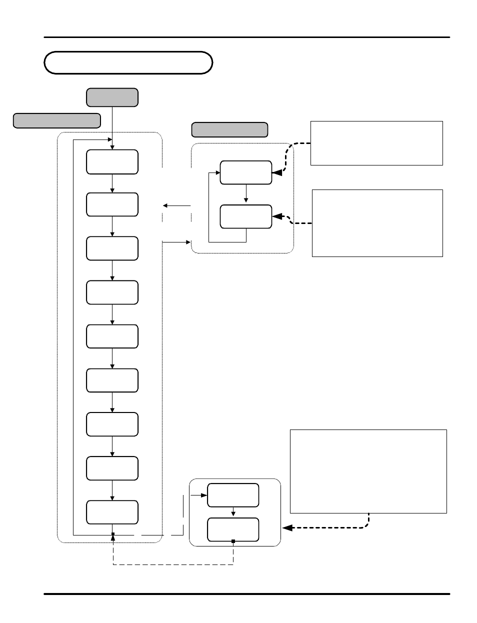
4. Operation Flow Chart
Operation Display
Power On
ENT
ENT
ENT
Group Display
S or T
S E T/ E NT
key for 3 s ec or
no keystroke for
60 se c
PV Display
"Stop"
ENT
S E T/ E NT
key for 3 se c
(note 1)
note 1: SP display reads 'STOP' when the controller outputs are off, such as when a
program is not running.
note 2: This is the default display when the controller turns on.
note 3: Output control display shows level of output as % of full output scale.
note 4: Displays program segment number in process.
note 5: Display of the time left that the current segment is running for.
note 6: The STEP feature is used to jump to the next program segment. Turning this
feature ON will immediately force the program to the next program segment.
note 7: Menu used to set the program to HOLD, and stop the program in its current state.
note 8: Displays the active set point while in HOLD. This set point may be changed,
altering the set point of the controller while in HOLD mode.
note 9: Displays the time left in the current segment while in HOLD. This time can be
changed, altering the time left in the segment when HOLD is turned off.
note 10: Only displayed when User Screen 1 is set by US1.
note 11: Only displayed when User Screen 2 is set by US2.
PV Value
SP Value
PV Value
OUT Value
"N.SEG"
Segment #
"R-TM"
Run Time
"STEP"
OFF
"HOLD"
OFF
"H.SP"
Prog SP
"H.TM"
Seg Time
US1
US2
ENT
ENT
ENT
PROG
STUP
This menu contains the parameter
used to setup the inputs and outputs
as well as the parameters for general
controller function. These must be
set prior to controller operation.
This menu contains parameters to set
the time unit, wait zones, program
patterns, end of program behavior,
and time signals.
US1 and US2 are set by the user to display
selected parameters in the operation display.
The parameters to be displayed are set from
parameters US1 and US2 in G.CTL. The
Table of D-Registers provides the number to
determine what parameter is displayed by
each. Parameters displayed here may be
altered in this display as they are normally.
(note 2)
(note 3)
(note 4)
(note 5)
(note 6)
(note 7)
(note 8)
(note 9)
*NOTE 10
*NOTE 11
ENT
PD550 Series Nova Programmable Process and Temperature Controller
Instruction Manual
14