Smart wireless thum adapter, Quick installation guide – Emerson 00825-0100-4075 User Manual
Page 8
Quick Installation Guide
00825-0100-4075, Rev DA
July 2011
Smart Wireless THUM Adapter
8
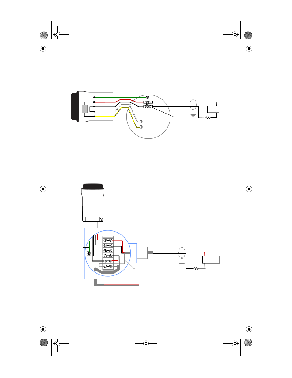
Figure 6. Direct Mount Wiring Diagram for 2-Wire Device
NOTE:
In order for the THUM Adapter to function properly there must be at least 250 Ohms
resistance in the loop. If the 4–20 mA loop does not have the required resistance, wire
a resistor as shown in Figure 8, 12, or 16 as applicable.
Figure 7. Remote Mount Wiring Diagram for 2-Wire Device
Splice Connector
Wired Device
4-20 mA Loop -
4-20 mA Loop +
Ground
- PWR / COMM
+ PWR / COMM
THUM Adapter
Green
Red
Black
White
Yellow
Load Resistor
250
Power
+
Supply
-
Remote Mount Housing
4-20 mA Loop -
4-20 mA Loop +
Ground
+ COMM
- COMM
THUM Adapter
Green
Red
Black
White
Yellow
To Wired Device
Shield Wire
Load Resistor
250
+
Power
-
Supply
4075_QIG_Rev_DA.fm Page 8 Wednesday, July 27, 2011 8:50 AM