Bench top configuration, Smart wireless thum adapter – Emerson 00825-0100-4075 User Manual
Page 4
Quick Installation Guide
00825-0100-4075, Rev DA
July 2011
Smart Wireless THUM Adapter
4
Power Supply
Minimum loop load of 250 Ohms.
The THUM Adapter communicates via and derives power from a standard 4-20 mA/HART
®
loop. The THUM Adapter causes a small voltage drop on the loop which is linear from 2.25
V at 3.5 mA to 1.2 V at 25 mA. Under fault conditions, the maximum voltage drop is 2.5 V.
The THUM Adapter will not affect the 4-20 mA signal under normal or fault conditions as
long as the loop has at least a 2.5 V margin at the maximum loop current (25 mA for a
typical 4-20 mA/HART device).
Limit the power supply to 0.5 Amps maximum, and voltage to 55 Vdc.
Load Resistor
If required, add a load resistor as shown in Figure 8, 12, and 16. The resistor should be
adequately rated for the application (1W minimum) and be compatible with the supplied
splice connector which accepts wire sizes from 14 to 22 AWG.
Loop
To ensure proper operation, the THUM Adapter should not be installed on a HART loop with
other active HART masters. HART masters that are active periodically, such as a field
communicator can be used on a loop with a THUM Adapter.
B
ENCH
TOP
C
ONFIGURATION
When performing bench top configuration it is suggested that you connect the THUM
Adapter to a wired device. If this is not possible, the following wiring diagrams can be used.
For bench top configuration, ensure that the power supply that you are using is limited to 0.5
Amps maximum.
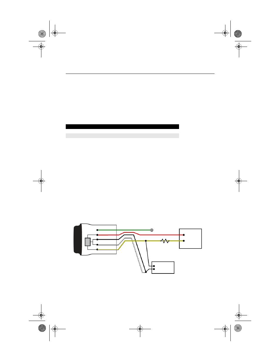
Figure 2. THUM Adapter Only, Powered by a Current Source (Such as a Fluke 744)
Loop Current
THUM Adapter voltage drop
3.5 mA
2.25 V
25 mA
1.2 V
Ground
-
20 mA
Current
Source
HART
Modem
THUM Adapter
Green
Red
Black
White
Yellow
+
250 Ohm Resistor not
required, but may be
used to verify current
4075_QIG_Rev_DA.fm Page 4 Wednesday, July 27, 2011 8:50 AM