Action, Verification, Installing the rectifier – Emerson NT5C06D User Manual
Page 28: Factory setting, Table 7 - rectifier settings, Procedure 2 - verification, Procedure 3 - rectifier installation procedure
28 Installation and start-up
UM5C06D ( 169-2071-504 ) P0831010 Standard 7.00 May 2001
Verification
After completing the wiring of the power shelf perform the following:
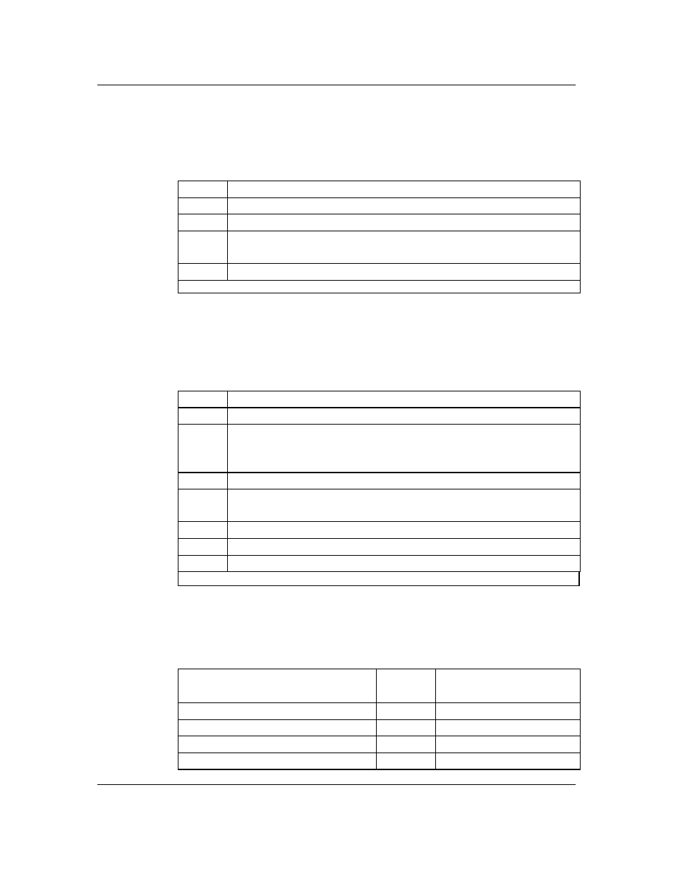
Procedure 2 - Verification
Step Action
1
Verify that the power shelf has been mechanically secured.
2
Verify that all the wiring performed is correct by using a voltmeter.
3
Verify that all connections are mechanically correct (that is, tight, correct
connector, correct marking etc.)
4
Reinstall the AC and DC junction box cover on the left and right sides.
end
-
Installing the rectifier
The NT5C06D rectifier is a plug-in unit intended for use in the MPS75
power shelf.
Procedure 3 - Rectifier installation procedure
Step Action
1
Release the clamping bar by loosening the two captive screws
2
Remove the blank panel for the rectifier to be installed (place a finger in the
hole, lift up, pull forward, then lower to disengage upper tabs from the shelf
top). Store the panel at the bottom of the shelf, under the rectifier.
3
Ensure that both AC and DC circuit breakers are in the OFF position.
4
Use a voltmeter to verify that the AC supply at the input of the shelf is 208
/ 240 V AC nominal.
5
Carefully slide the rectifier in position on top of the stored blank panel.
6
Insure that the rectifier is firmly slid and seated into position.
7
Reinstall the clamping bar by securing the two captive screws.
end
Factory setting
The rectifier is factory set as indicated in Table 7.
Table 7 - Rectifier settings
Load
Sharing
Slope load sharing method
Rectifier Output Voltage (FLOAT)
54.5 V DC ± 0.1 V
Rectifier Output Voltage (EQUALIZE)
55.2 V DC ± 0.1 V
Rectifier High Voltage Shutdown (HVSD) 59.0 V DC ± 0.1 V
Rectifier Output Current Limit
30 A
± 0.5 A