Dc conductors installation, Figure 5 - power shelf individual ac connection, Caution – Emerson NT5C06D User Manual
Page 22
22 Installation and start-up
UM5C06D ( 169-2071-504 ) P0831010 Standard 7.00 May 2001
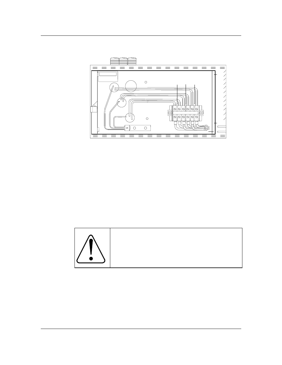
Figure 5 - Power shelf individual AC connection
FR GRD
POS 3 POS 2 POS 1
L1 L2 L1 L2 L1 L2
6 5 4 3 2 1
When cabling the AC to the power shelf, make sure that each corresponding
safety ground wire is properly connected to the terminal designated FR
GND.
This grounding is proven to be sufficient, but for systems requiring an extra
ground connection, an 8 AWG cable wire (color green, insulation 105°C) can
be installed in addition to the existing cable and be connected to an external
system ground. The new ground wire can be installed on one of the existing
FR GND terminal screws located inside the power shelf with a 0.25-inch
terminating ring lug. The wire must be routed along the top back of the shelf
and come out the back opening on the right DC cabling side. Make sure that
the wire does not interfere with the rectifier connections.
CAUTION
Do not insert fuses or operate circuit breakers (switches)
until the entire system has been assembled and you have
been instructed to do so in the appropriate procedure.
DC Conductors Installation
Make the connections at the power shelf prior to connecting DC leads to the
battery or the distribution (load). Permanently connect the shelf to the
interconnect and distribution panel using the properly-size cable by referring
to Table 4. The DC output of the rectifiers is terminated on two busbars
(RTN & -48 V) located on the right side of the shelf. The length of the
conductors should be minimized to reduce voltage drops and interference.