Kl h g, Installation of lower panel, Installation of side tiles – MCZ Athos MULTIAIR User Manual
Page 21: Fase 1 fase 2 fase 3 fase 4
PELLET STOVES
Chapter 3
INSTALLATION AND USE MANUAL
page
21
Installation and assembly
Technical service - Rights reserved MCZ S.p.A. - Reproduction prohibited
K
L
H
G
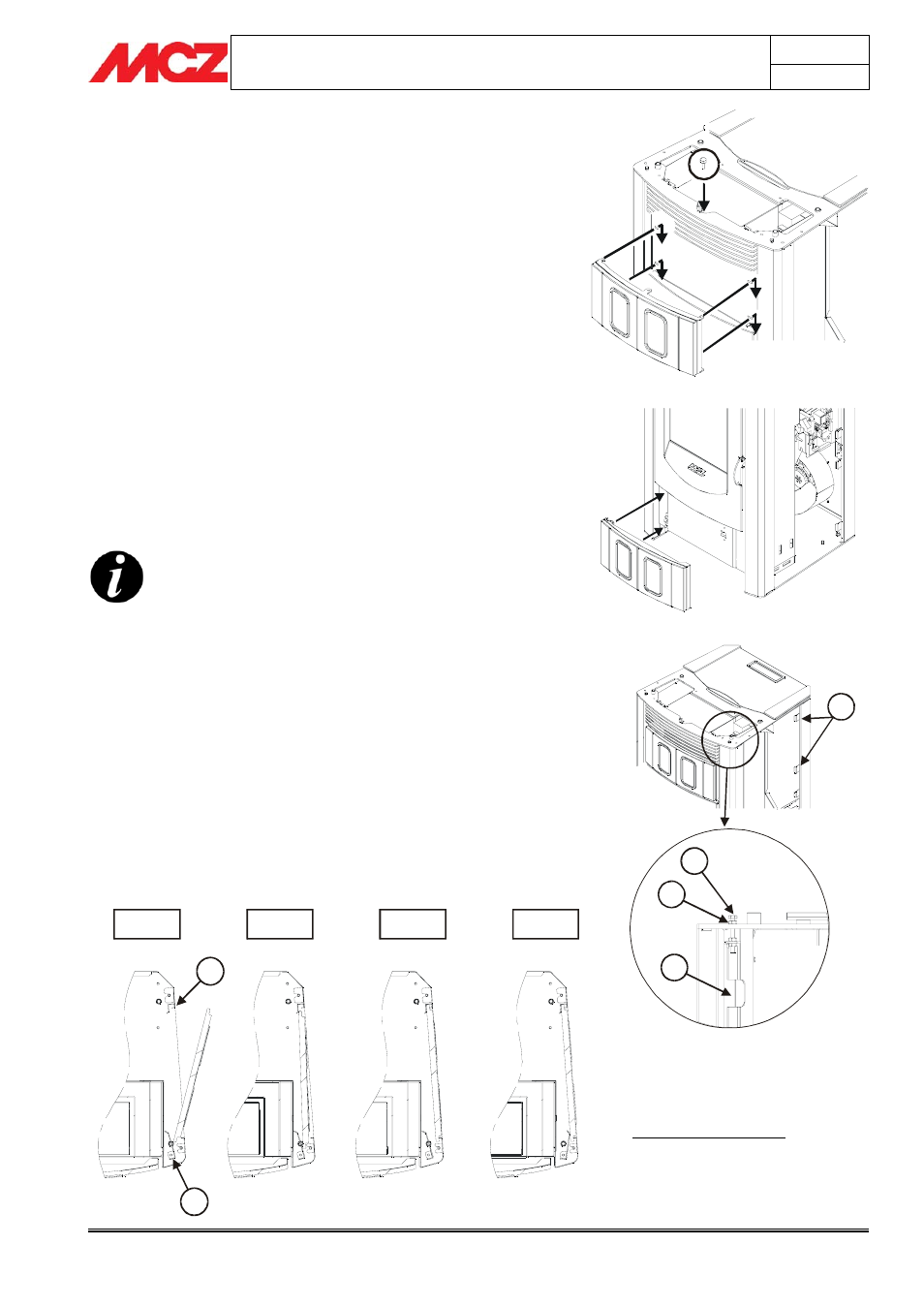
3.4. INSTALLATION OF CERAMIC CLADDING FOR
POLAR AND NOVA
3.4.1. Installation of upper panel
Take the panel and insert it so that the side hooks are inserted in the
slots at the top of the frame. When insertion is complete, push down
and secure everything in place using the provided self-threading screw.
Figure 7
3.4.2. Installation of lower panel
Remove the two pre-installed nuts in the lower part of the frame
alongside the ash compartment door. Take the lower panel, open the
hinge and install it, using the two screws which you freed when you
removed the nuts. Check the alignment of the panel and tighten the
nuts.
Figure 8
3.4.3. Installation of side tiles
THE ASSEMBLY OF THE TILES MUST ALWAYS BEGIN
FROM THE BOTTOM.
1. Turn the screw K so that the rod H comes into contact with the
structure. Insert the tile first from the side of the rod H, and
then insert the opposite part in the housing in the fixed hooks
G.
Figure 10- phase 1
2. Turn the tile towards the exterior of the stove so that the front
edge that remains free rests on the upright.
Figure 10 - phase
2
3. Repeat steps 1-2-3 for all the tiles of the side.
Figure 10 -
phase 3
4. Turn the screw K so that the connected rod H pushes the tile
towards the upright. Use another wrench to tighten nut L to
permanently secure the system.
Figure 10 - phase 4
5. Repeat the operations described on the other side.
Fase 1
Fase 2
Fase 3
Fase 4
H
G
Legend for Figures 9 and 10
G - Rear fixed hooks
H - Front blocking rod
L - Blocking nut
K - Blocking screw
Figure 7 – Installation of upper front panel
Figure 8 – Installation of lower front panel
Figure 9 – Side view of the fastening system
of the lateral ceramics
Figure 10 – Top view of fastening system of
the lateral ceramics