MCZ Athos MULTIAIR User Manual
Page 20
PELLET STOVES
Chapter 3
INSTALLATION AND USE MANUAL
page
20
Installation and assembly
Technical service - Rights reserved MCZ S.p.A. - Reproduction prohibited
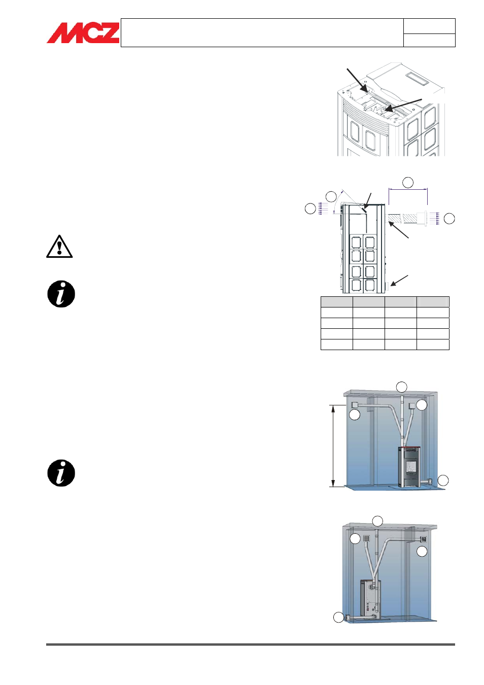
3.3. CONNECTIONS OF HOT AIR DUCTS FOR
POLAR/NOVA/ATHOS MULTIAIR MODEL
Once the stove is in position, you can begin installation of the hot air
ducts.
First of all, select the amount of hot air that you want to come out of
the front and the back of the stove.
This simple operation is possible by adjusting the mechanical deflector
located on the upper part of the stove, under the ceramic top,
(
Figure 3) to the desired position, using the provided hook. The greater
the opening, the more air will be directed to the front part and less to
the back, and vice versa.
For further clarity,
Figure 4 shows the partitioning of hot air between
the two outlets (front and rear) at maximum ventilation power and
taking one duct into account.
Do not adjust the upper deflector when the stove is
in operation or if you are not wearing protective
gloves: DANGER OF BURNS. Outlet air normally has
an average temperature of
≥ 70°C
NEVER COMPLETELY CLOSE THE REAR AIR OUTLET!!!
You should not send all of the hot air to the front
part of the stove. The high amount of air in
circulation would cause noisy turbulence in the air
exchanger of stove, and it would also cause the
structure to overheat substantially. You can however
completely close the front outlet (deflector) and send
all the air to the rear outlet.
Once you have adjusted the deflector, connect the rear flange for hot
air outlet
(Figure 4) to ducts and nozzles. You can use special fittings
from MCZ that divert the flow into several nozzles and which may be
cemented into the wall. The rear hot air outlet has a diameter of 100
mm. Therefore, you can use pipes of the same or slightly smaller
diameter (80 mm) to be cemented into the air spaces of the home. A
pipe which is inserted in the wall must be properly insulated so that it
does not lose heat and so that air outlet is silent.
You should use ducts of the same length so that the
air is evenly distributed. Otherwise, the air will tend
to flow through the shortest or least twisted ducts
Shown here (
Figures 5 and 6) is a simple example of ducting, seen both
from in front of and in back of the stove
For better air circulation in the room, it is advisable also to connect with
the exterior the rear air inlet flange (
Figure 6 – A). This connection is
not required if the room where the product is installed is sufficiently
ventilated.
Legend for Figures 5 and 6
A = cold air inlet - B = hot air outlet nozzles and ducts - C = smoke outlet pipe
A
B
J
K
0 m
Min
30%
70%
0 m
MAX
50%
50%
4 m
Min
40%
60%
4 m
MAX
60%
40%
Figure 3 – Adjustment of upper front deflector
Figure 4 – Rear/front partitioning of hot air
Figure 5 – Front view of air outlet system
Figure 6 – Rear view of air outlet system
A
B
B
C
B
A
B
C
M
A
X
2
m
t.
K
A
B
J
Deflector
Hot air outlet
flange
Cold air outlet
flange
Hook
Deflector