Fig.3 fig.4 – Sealey MM405 User Manual
Page 2
Function
Range
Resolution
Accuracy
DC Current
0~ ±200A
0.1A
± (2.8% reading + 8 digits)
AC Current
0~200A
0.1A
± (3.0% reading + 8 digits)
Frequency
(Auto-ranging)
40~51Hz
51~510z
0.51~1kHz
0.01Hz
0.1Hz
0.001kHz
± (1.2% reading + 5 digits)
Input sensitivity: 2.5A AC RMS
min.
3.
SPECIFICATION
4.
OPERATION
Clamp size . . . . . . . . . . . . . . . . . . . . . . . . . . . . . . . .Opening 18mm approx.
Low Battery Indication . . . . . . . . . . . . . . . . . . . . . . .BAT is displayed.
Overange Indication . . . . . . . . . . . . . . . . . . . . . . . . .OL is displayed.
Measurements Rate . . . . . . . . . . . . . . . . . . . . . . . . .2 per second, nominal.
Display . . . . . . . . . . . . . . . . . . . . . . . . . . . . . . . . . . .3-2/3 digits (2400 counts) LCD.
AC Current bandwidth . . . . . . . . . . . . . . . . . . . . . . .50/60Hz (AAC).
Operating Temperature . . . . . . . . . . . . . . . . . . . . . .14 - 122°F (-10-50°C).
Storage Temperature . . . . . . . . . . . . . . . . . . . . . . . .-14 - 140°F (-30 - 60°C).
Relative Humidity . . . . . . . . . . . . . . . . . . . . . . . . . . .90% (0° - 30°C), 75% (30° - 40°C), 45% (40° - 50°C).
Altitude . . . . . . . . . . . . . . . . . . . . . . . . . . . . . . . . . . .Operating: 3000m, storage 10,000m.
Over Voltage . . . . . . . . . . . . . . . . . . . . . . . . . . . . . . .Category II 600V.
Battery . . . . . . . . . . . . . . . . . . . . . . . . . . . . . . . . . . .Two 1.5V AAA Batteries.
Auto OFF . . . . . . . . . . . . . . . . . . . . . . . . . . . . . . . . .Aprox. 7 minutes.
Dimensions/Weight . . . . . . . . . . . . . . . . . . . . . . . . .164x65x32mm/175g.
Safety . . . . . . . . . . . . . . . . . . . . . . . . . . . . . . . . . . . .For indoor use and in accordance with Overvoltage Category
. . . . . . . . . . . . . . . . . . . . . . . . . . . . . . . . . . . . . . . . .II, Pollution Degree 2. Category II includes local level,
. . . . . . . . . . . . . . . . . . . . . . . . . . . . . . . . . . . . . . . . .appliance, portable equipment, etc, with transient
. . . . . . . . . . . . . . . . . . . . . . . . . . . . . . . . . . . . . . . . .overvoltage less than Overvoltage Category II.
p WARNING! Read and understand all warnings and precaution statements listed in the safety section of this
operation manual prior to using this meter. Set the function select switch to OFF position when meter not in use.
4.1
AC Current Measurements.
4.1.1
Set the Function switch to the ACA range.
4.1.2
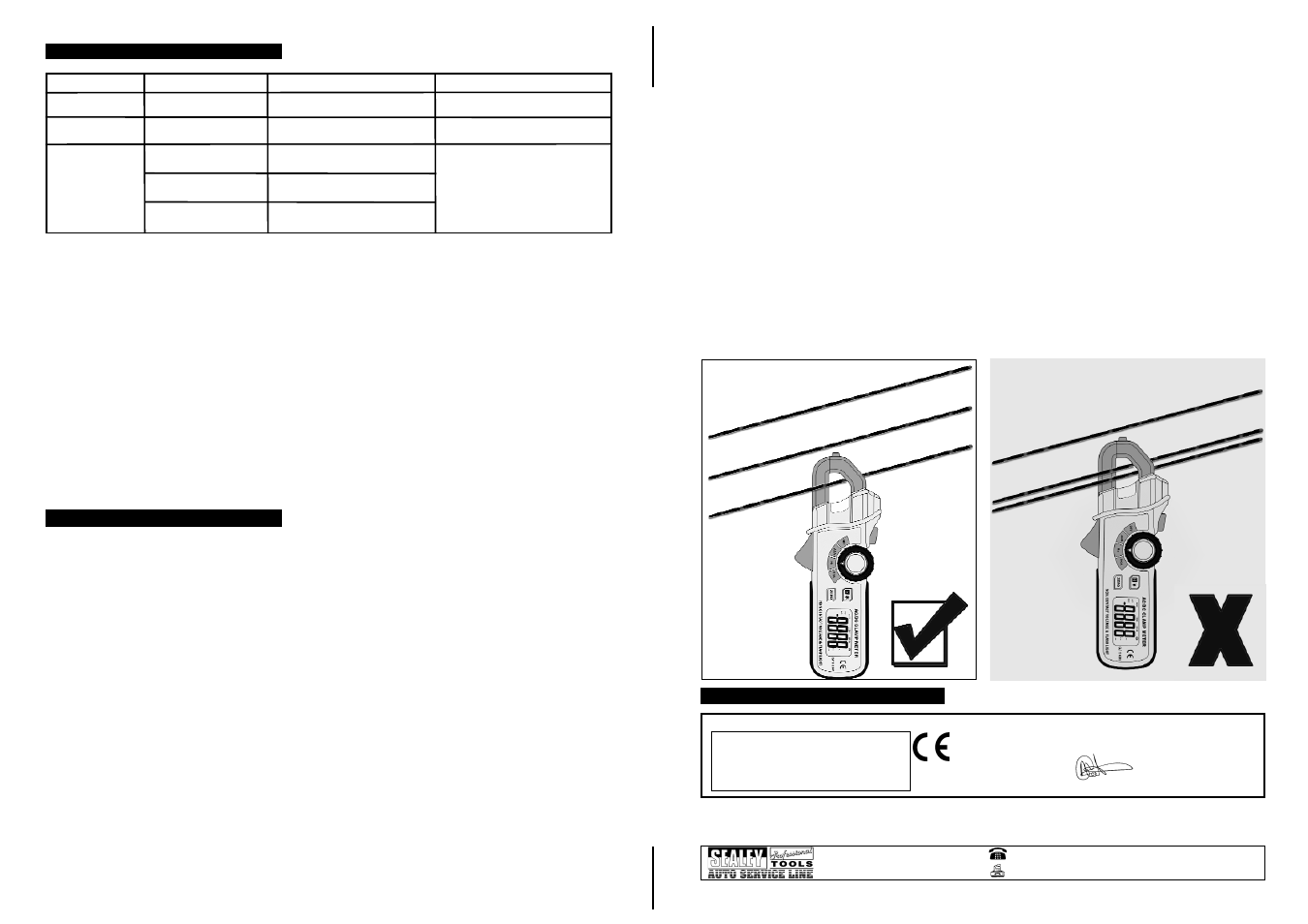
Press the trigger to open the jaw. Fully enclose one conductor (fig.3) to be measured.
4.1.3
The clamp meter LCD will display the reading.
NOTE:
DO NOT enclose more than one conductor at any time (fig.4).
4.2
DC Current Measurements.
4.2.1
Set the Function switch to the DCA range.
4.2.2
Press the trigger to open the jaw. Fully enclose one conductor (fig.3) to be measured.
4.2.3
Press the Zero button to zero the meter in the DCA mode only.
4.2.4
The clamp meter LCD will display the reading.
NOTE:
DO NOT enclose more than one conductor at any time (fig.4).
4.3
Frequency Measurements.
4.3.1
Set the rotary function switch to the Hz position.
4.3.2
Press the trigger to open the jaws. Fully enclose one conductor (fig.3) to be measured.
4.3.3
Read the frequency on the display.
NOTE:
DO NOT enclose more than one conductor at any time (fig.4) .
4.4
Data Hold.
4.4.1
To freeze the LCD meter reading, press the data hold button. While data hold is active, the HOLD
display icon appears on the LCD. Press the data hold button again to return to normal operation.
NOTE:
The HOLD feature will activate when the Backlight is turned on. Press the hold key again to exit hold.
4.5
Backlight.
4.5.1
The backlight function illuminates the display and is used when the ambient light is low to permit
viewing of the displayed reading.
4.6
Zero Button.
4.6.1
For DCA Zero & Offset adjustment.
4.7
Voltage Detection.
4.7.1
Intended to check for the presence of AC voltage, signalling the user with RED LIGHT illuminating
between the clamp jaws.
p WARNING! The voltage detector is intended to check for the presence of AC voltage, not to prove that a
power circuit is dead.
4.8
Flash Light.
4.8.1
Press and hold the red button on the upper side of the meter, this will light the lamp near the clamp and
provide illumination on the work subject.
4.8.2
Release the button and the light will turn off.
4.9
Battery Replacement
4.9.1
Remove the philips screw from the battery cover on the rear of the clamp meter.
4.9.2
Open the battery compartment.
4.9.3
Replace the two AAA batteries (UM4 RO3).
4.9.4
Re-assemble the meter.
Fig.3
Fig.4
01284 757500
01284 703534
E-mail: [email protected]
Sole UK Distributor
Sealey Group,
Bury St. Edmunds, Suffolk.
Web address: www.sealey.co.uk
5.
DECLARATION OF CONFORMITY
NOTE: It is our policy to continually improve products and as such we reserve the right to alter data, specifications and component parts without prior notice.
IMPORTANT: No liability is accepted for incorrect use of this equipment.
WARRANTY: Guarantee is 12 months from purchase date, proof of which will be required for any claim.
INFORMATION: For a copy of our latest catalogue and promotions call us on 01284 757525 and leave your full name and address, including postcode.
Declaration of Conformity We, the sole UK importer, declare that the product listed below is in conformity with the following standards and directives.
MINI AC/DC CLAMP METER
Model: MM405
89/336/EEC EMC Directive
93/68/EEC CE Marking Directive
For Jack Sealey Ltd. Sole UK importer of Sealey Professional Tools.
The construction file for this product is held by the Manufacturer and may be inspected,
by a national authority, upon request to Jack Sealey Ltd.
Signed by Mark Sweetman
22nd April 2005
MM405 - 1 - 260505
MM405 - 1 - 260505