Maintenance 4. specifications – Sealey MM20 User Manual
Page 2
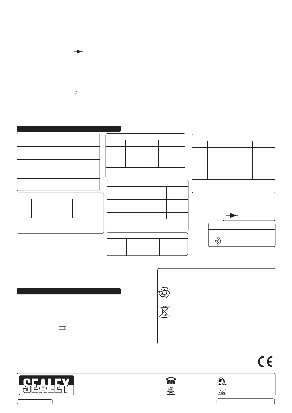
AC VOLTAGE
Range
Accuracy
Resolution
200V
± 2% of rdg ± 2 digits
100mV
600V
± 2% of rdg ± 2 digits
1V
Overload protection: 600V DC or 600V rms AC.
Response: Average responding, calibrated in rms of a
sine wave. Frequency range: 40Hz - 400Hz
TEMPERATURE
Range
Accuracy
Resolution
-40°C to
400°C
± 1.0% of rdg
± 3°C
1°C
400°C to
1000°C
± 2.0% of rdg
± 3°C
1°C
Overload protection: 220V rms AC
DIODE TEST
Range
Description
Display Approx.
Voltage Drop
CONTINUITY TEST
Range
Description
Buzzes if resistance
is below 70Ω
TRANSISTOR h
FE
TEST
Range
Displaying range
Test Condition
(NPN or
PNP)
0 - 1000
Current: 10µA
Vce: 3V
3.3.
MEASURING RESISTANCE
3.3.1. Connect the black lead to the COM input socket and the red test lead to the the VΩmA input socket (the polarity of the red lead is ‘+’).
WARNING!
When checking in-circuit resistance, ensure that the circuit under test has all power removed and all capacitors have been fully discharged before testing.
3.3.2. Set the rotary switch to the required Ω range and connect the test probes across the resistance under measurement.
3.3.3. When measuring resistance over 1MΩ, the meter may take a few seconds to get a stable reading. This is normal for high resistance measurements.
3.4.
DIODE TESTING
3.4.1. Connect the black lead to the COM input socket and the red lead to the VΩmA input socket (the polarity of the red lead is ‘+’).
3.4.2. Set the rotary switch to the position and connect the red lead to the anode and the black lead to the cathode of the diode under test.
3.4.3. The meter will show the approximate forward voltage drop of the diode in mV. If the leads are reverse connected, ‘1’ is displayed.
3.5.
TRANSISTOR TESTING
3.5.1. Determine whether the transistor to be tested is NPN or PNP type and set the rotary switch to the appropriate NPN or PNP - h
FE
position.
3.5.2. Locate the Emitter, Base and Collector leads. Insert the leads of the transistor into the correct holes in the tester's front panel.
3.5.3. The meter will show the approximate h
FE
value (0-1000) at test conditions of (approx) base current 10µA and Vce 3.0V.
3.6.
AUDIBLE CONTINUITY TEST
3.6.1. Connect the black lead to the COM input socket and the red lead to the VΩmA input socket (the polarity of the red lead is ‘+’).
3.6.2. Set the rotary switch to the position and connect the test leads across the two points of the circuit under test.
3.6.3. If continuity exists (i.e. resistance is less than 70Ω), the built-in buzzer will sound.
3.7.
MEASURING TEMPERATURE
3.7.1. Insert the red lead of the K-type thermocouple into the VΩmA input socket on the front panel and the black lead into the COM input socket.
3.7.2. Set the rotary switch to the
°C position.
3.7.3. Touch the object to be measured with the thermocouple probe and the ambient temperature will be displayed.
WARNING! To avoid electric shock, ensure that the thermocouple has been removed before changing to another function measurement.
5. MAINTENANCE
4. SPECIFICATIONS
WARNING! Before attempting to open the case, ensure that the test leads have
been disconnected from measurement circuits to avoid electric shock hazard.
5.1.
A fuse usually only blows due to operator error. To replace the fuse, remove the
protective rubber boot and the two screws from the rear of the meter. Lift off the
rear cover, replace the fuse and re-assemble the tester in reverse order, ensuring
that the rear cover engages with the two lugs at the top of the tester.
WARNING! ALWAYS replace a fuse with one of the correct rating (200mA/250V).
5.2.
If the battery sign appears on the LCD display, it indicates that the battery
should be replaced. Repeat the steps detailed in section 5.1. to remove the rear
cover, replace the battery (9V PP9 type) by unplugging the old one and plugging
a new one in and re-assemble in reverse order.
5.3.
Occasionally clean the multimeter's casing using a slightly moistened cloth.
4.1.
Accuracy Calculation
Example: Test reading on 200Vdc range is 56.4V. Accuracy is ±0.8% of
reading ±3 digits. Reading ±3 digit = 56.4 ±3 on the last figure i.e. 56.1 to
56.7V. ±0.8% on this range gives 56.1 - 0.8% to 56.7 + 0.8% or 55.6 to
57.1V. Therefore the actual voltage lies between 55.6 and 57.1V.
Note: Accuracy is specified for a period of one year after calibration and at 23°C
±
5
°C with a relative humidity of less than 75%.
DC VOLTAGE
Range
Accuracy
Resolution
200mV ±0.5% of reading ±2 digits
100
µV
2V
±0.8% of reading ±3 digits
1mV
20V
±0.8% of reading ±3 digits
10mV
200V
±0.8% of reading ±3 digits
100mV
600V
±0.8% of reading ±5 digits
1V
Overload protection: 220V rms AC for 200mV range
and 600V DC or 600V rms AC for other ranges.
DC CURRENT
Range
Accuracy
Resolution
2mA
±1.0% of reading ±2 digits
1µA
20mA
±1.0% of reading ±2 digits
10µA
200mA ±1.2% of reading ±2 digits
100µA
10A
±2.0% of reading ±2 digits
10mA
Overload protection: 200mA/250V fuse
Measuring Voltage drop: 200mV
RESISTANCE
Range
Accuracy
Resolution
200Ω
±0.8% of reading ±5 digits
0.1Ω
2kΩ
±0.8% of reading ±2 digits
1Ω
20kΩ
±0.8% of reading ±2 digits
10Ω
200kΩ
±0.8% of reading ±2 digits
100Ω
2MΩ
±1.2% of reading ±3 digits
1kΩ
Maximum Open Circuit Voltage: 2.8V
Overload protection: 220V rms for a maximum of
10 seconds for all ranges.
Environmental Protection.
Recycle unwanted materials instead of disposing of them as
waste. All tools, accessories and packaging should be sorted,
taken to a recycle centre and disposed of in a manner which is
compatible with the environment.
When the product is no longer required, it must be disposed of in an
environmentally protective way.
Battery Removal
1. See Section 5.2.
2. Remove and dispose of according to local authority guidelines.
Under the Waste Batteries and Accumulators Regulations 2009,
Jack Sealey Ltd are required to inform potential purchasers of
products containing batteries (as defined within these regulations),
that they are registered with Valpak’s registered compliance
scheme. Jack Sealey Ltd’s Batteries Producer Registration
Number (BPRN) is BPRN00705
NOTE: It is our policy to continually improve products and as such we reserve the right to alter data, specifications and component parts without prior notice.
IMPORTANT: No liability is accepted for incorrect use of this product.
WARRANTY: Guarantee is 12 months from purchase date, proof of which will be required for any claim.
01284 757500
01284 703534
Sole UK Distributor, Sealey Group,
Kempson Way, Suffolk Business Park
,
Bury St. Edmunds, Suffolk,
IP32 7AR
www.sealey.co.uk
Original Language Version
© Jack Sealey Limited
MM20.V3 Issue No: 4(S) - 12/05/15