Remove screws to access battery and fuses – Sealey MM19 User Manual
Page 2
Original Language Version
High quality general purpose multimeter with a large (46x25mm),
clear and easy-to-read LCD display. Supplied with test leads.
Measures:
• AC and DC Voltage
• DC Current
• Resistance
• Diode/Transistor Verification Model
2. FEATURES
WARNING! NEVER apply voltage or current to the meter that exceeds the specified maximum stated.
WARNING!
USE EXTREME CAUTION when working with
high voltages.
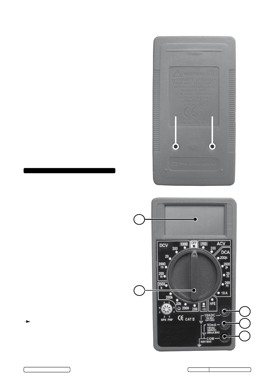
1.
Function Switch
2.
LCD Display
3.
Common Jack
4.
V.Ω.mA Jack
5.
10A Jack
6.
Note: Fuse and battery compartment are
at the rear of the unit.
SYMBOLS AND ANNUNCIATORS
•)))
Continuity
Diode Test
µ
Micro (amps)
m
Milli (volts, amps)
k
Kilo (ohms)
Ω
Ohms
DCV
Volts Direct Current
ACV
Volts Alternating Current
DCA
Amps Direct Current
hFE
Transistor Measurement
1.4. BATTERY INSTALLATION
WARNING!
To avoid electric shock, disconnect the test
leads from any source of voltage before removing the battery
cover.
Disconnect the test leads from the meter.
Open the battery cover by loosening the two cover screws
using a Phillips head screwdriver.
Insert the battery into battery holder, observing the correct
polarity.
Replace the battery cover. Secure with the screws.
WARNING! To avoid electric shock, do not operate the meter
until the battery cover is in place and fastened securely.
NOTE! If your meter does not work properly, check the fuses and
battery to make sure that they are still good and that they are
properly inserted.
1
2
3
4
5
REMOVE SCREWS
TO ACCESS
BATTERY AND
FUSES
© Jack Sealey Limited
MM19.V3 Issue No: 5(I) - 16/06/14