Fig.2 – Sealey TA050 User Manual
Page 2
3.2.3. Press the MEAS button once to turn the unit on. To switch
from one measurement group to the other hold down the
MODE button for three seconds. The display will alternate
between RPM (Group one) and REV (Group two). Release
the button when the display shows the group you require.
Press the MODE button repeatedly to cycle through the
options in each group (as shown overleaf) until you reach the
required measurement.
3.3.
NON-CONTACT MEASUREMENT
3.3.1. In order to do a non-contact measurement the rotating object
must have a segment of reflective, self adhesive tape
attached to it. The tape should be attached as close to the
outer edge of the object as possible. Cut a 1/2” square from
the tape provided and apply to the object.
3.3.2. To obtain an accurate reading the non-reflective area must
always be greater than the reflective area.
3.3.3. If the whole object, such as a shaft, is normally reflective it
must be covered in black tape or painted black before the
reflective tape is applied.
3.3.4. When measuring very low rpm it may be necessary to apply
several reflective marks equally around the circumference of
the object. When a reading is taken it should then be divided
by the number of reflective marks in order to get a true reading.
3.3.5. TO TAKE A READING. Hold the unit about 6” (15cm) from the
rotating object. Press and hold the MEAS button and direct the
red spot of the laser beam onto the rotating object in the area
where the self adhesive tape was applied. After about 4
seconds the scanning symbol will be shown at the top of the
display (See fig.4) and a reading will appear in accordance with
the units of measurement previously selected. To store the
value(s) press the MEM button once whilst the MEAS button is
still held down. For more information refer to 3.5 DATA
STORAGE and 3.6 DATA RECALL.
3.4.
CONTACT MEASUREMENT
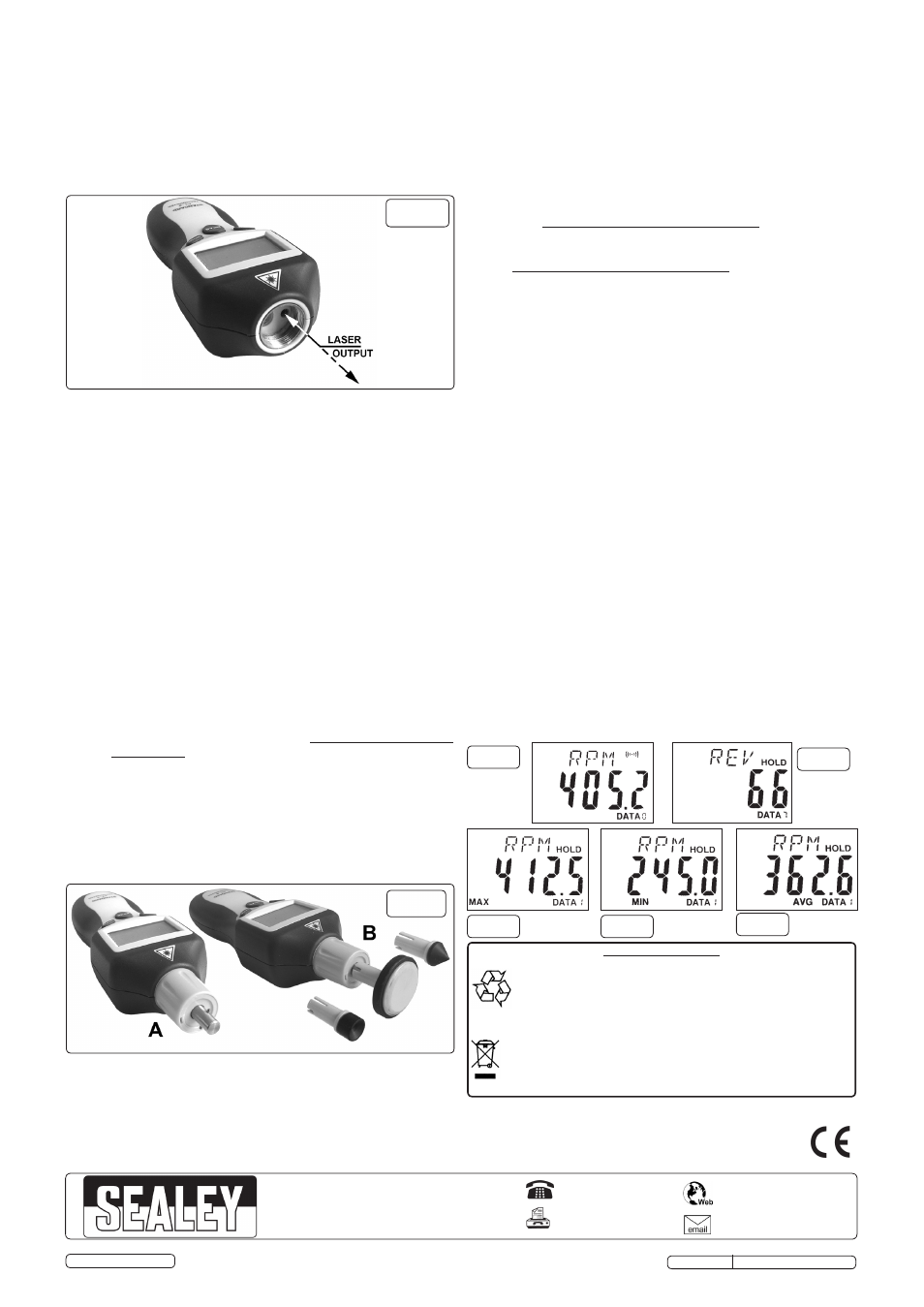
3.4.1. Screw the contact adaptor into the front aperture of the
tachometer as shown in fig.3-A.
3.4.2. Choose one of the contact drivers shown in fig.3-B and push
it onto the adaptor shaft ensuring that the slots in the driver
pass over the drive pin in the end of the adaptor shaft.
fig.4
fig.5
fig.6
fig.7
fig.8
fig.3
3.4.3. Before using the tachometer in a contact situation do a risk
assessment in the area you will be working in to ensure that
you will not inadvertently come into contact with any other
moving parts whilst taking the reading you require.
3.4.4. TO TAKE A READING, press and hold down the MEAS button
and bring the rubber part of the driver gently into contact with
the moving object. After about 4 seconds the scanning symbol
will be shown at the top of the display (See fig.4) and a reading
will appear in accordance with the units of measurement
previously selected. To store the value(s) press the MEM button
once
whilst the MEAS button is still held down.
3.5.
DATA STORAGE
3.5.1. To store the value(s) shown on display press the MEM button once
whilst the MEAS button is still held down.
3.5.2. The reading will be stored in one of ten data set locations.
One data set consists of a MAX data figure, a MIN data
figure, and an AVERAGE data figure. Only measurements
that can vary (such as RPM) will record as a set. Non variable
measurements such as REV will only record as a single
figure.
See fig.5.
3.5.3. Once data set ‘0’ has been used the system will automatically
advance to the next available memory location. When all ten
locations are full (0 to 9), new sets of data will begin to
overwrite the original readings.
3.6.
DATA RECALL
3.6.1. Press the MEAS button once to turn the unit on. Press the
MEM button once to display the current memory location in the
bottom right hand corner of the display.
3.6.2. If no data has been recorded for this location, another press
of the button will advance the display to the next memory
location.
3.6.3. When a memory location that contains data is selected the
reading will show in the centre of the display and the
appropriate unit of measurement will be shown at the top of
the display.
3.6.4. If maximum, minimum and average figures have been
recorded for a variable unit of measurement such as RPM,
the first measurement will be displayed with the word MAX
appearing at the bottom of the display. Press the MEM button
again to see the MIN measurement and press the button
again to see the AVG measurement. See figs. 6, 7 & 8. The
next press of the MEM button will advance the display to the
next memory location.
3.6.5. If no buttons are pressed for 15 seconds the unit will
automatically switch off.
fig.2
TA050 Issue No: 3(L) - 04/08/14
Environmental Protection.
Recycle unwanted materials instead of disposing of them as waste. All tools,
accessories and packaging should be sorted, taken to a recycle centre and
disposed of in a manner which is compatible with the environment.
When the product is no longer required, it must be disposed of in
an environmentally protective way. Contact your local solid waste authority for
recycling information.
WARNING: Do not dispose of by fire.This could result in an explosion.
Before disposing of battery, cover exposed terminals with heavy duty electrical
tape to prevent shorting.
DO NOT expose battery to intense heat or fire as this could cause an explosion.
NOTE: It is our policy to continually improve products and as such we reserve the right to alter data, specifications and component parts without prior notice.
IMPORTANT: No liability is accepted for incorrect use of this product.
WARRANTY: Guarantee is 12 months from purchase date, proof of which will be required for any claim.
INFORMATION: For a copy of our latest catalogue and promotions call us on 01284 757525 and leave your full name and address, including postcode.
01284 757500
01284 703534
Sole UK Distributor, Sealey Group,
Kempson Way, Suffolk Business Park
,
Bury St. Edmunds, Suffolk,
IP32 7AR
www.sealey.co.uk
Original Language Version
© Jack Sealey Limited