Sealey SM354CE User Manual
Page 5
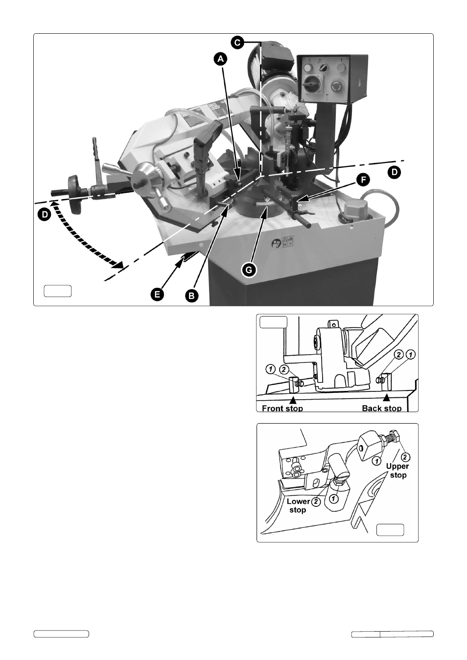
4.8 ADJUSTING THE BLADE GUIDE (See Fig.9)
4.8.1 The blade guide nearest to the motor is fixed and cannot be
adjusted.
4.8.2 In order to adjust the other blade guide first loosen the socket
cap bolt 'A' seen above using a 10mm hex. key. Once the
clamp block is loose, the blade guide can be moved in or out
with the rod 'B'. The blade guide should be set as close as
possible to the piece being cut without interfering with it or the
vice.
4.8.3 Retighten the socket cap bolt.
4.5 CUTTING AT AN ANGLE (See Fig.9)
4.5.1 In order to cut at an angle, the vice remains where it is and the
whole bow assembly pivots round on the machine bed. Line
'D---D' as shown in Fig.9 above represents the line of the blade
before the bow is rotated.
4.5.2 Before the bow can be rotated it must be unlocked by moving
the lever on the left hand face of the machine bed 'E' towards
the rear of the machine. See also 28 in Fig.4. The bow will now
pivot around line 'C' and can be set at any angle between 0
and 45° using the scale mounted around the main pivot seen
at 'G' above in Fig.9. Additionally the machine will cut at 60°
but the blade must be lifted over an area of solid metal and
lowered back into the 60° groove. The area of metal between
45° and 60° is necessary to give adequate support to the
workpiece either side of the blade especially on round sections.
4.5.3 Lock the bow at the chosen angle by moving the locking lever
back towards the front of the machine bed.
4.5.4 Lift the bow upwards from the vice and lock its position with the
tap on the hydraulic unit.
4.5.5 Set the position of the stop bracket 'F' and clamp the material
to be cut in the vice.
4.6 ADJUSTING THE BOW PIVOT TRAVEL LIMITS (See Fig.10)
4.6.1 Unlock the main pivot by moving the lever 'E' seen in Fig.9
towards the back of the machine bed.
4.6.2 The front stop seen in Fig.10 should be used to check that the
blade is at 90° to the vice. Place a small set square between
the blade and the fixed face of the vice. Loosen the hex nut '1'
and wind the bolt '2' in or out until 90° is achieved. Tighten the
hex nut '1'. Lock the main pivot using lever 'E'.
4.6.3 The back stop seen in Fig.10 limits the rotation of the bow to
60°. This is factory set and would not normally need adjusting.
Do not allow the bow to pivot beyond 60°.
4.7 ADJUSTING THE BOW RETURN STROKE (See Fig.11)
4.7.1 The lower stop seen in fig.11 is used to control the limit of
downward movement of the bow. This is factory set to prevent
the blade touching the vice and should not normally require
adjustment. The blade cover is shown removed in Fig.11.
4.7.2 The upper stop seen in fig.11 is used to control the upper limit
of movement of the bow. This is factory set and would not
normally need adjusting.
Fig.9
Fig.10
Fig.11
Original Language Version
SM354CE Issue: 3(SP) - 29/09/14
© Jack Sealey Limited