Fig.5 fig.6, Fig.7 fig.8 – Sealey SM354CE User Manual
Page 4
bed where it flows to the lower level and returns to the coolant
tank through the grill situated above it for recirculation.
4.1.3 The coolant tank can be first filled by pouring the liquid directly
through the grill. When the coolant becomes dirty and particle
laden it can be drained from the tank through a drain plug
situated at the bottom edge of the machine bed on the right
hand side. Remember to replace the drain plug before filling
with fresh coolant.
4.2
HYDRAULIC BOW DAMPER
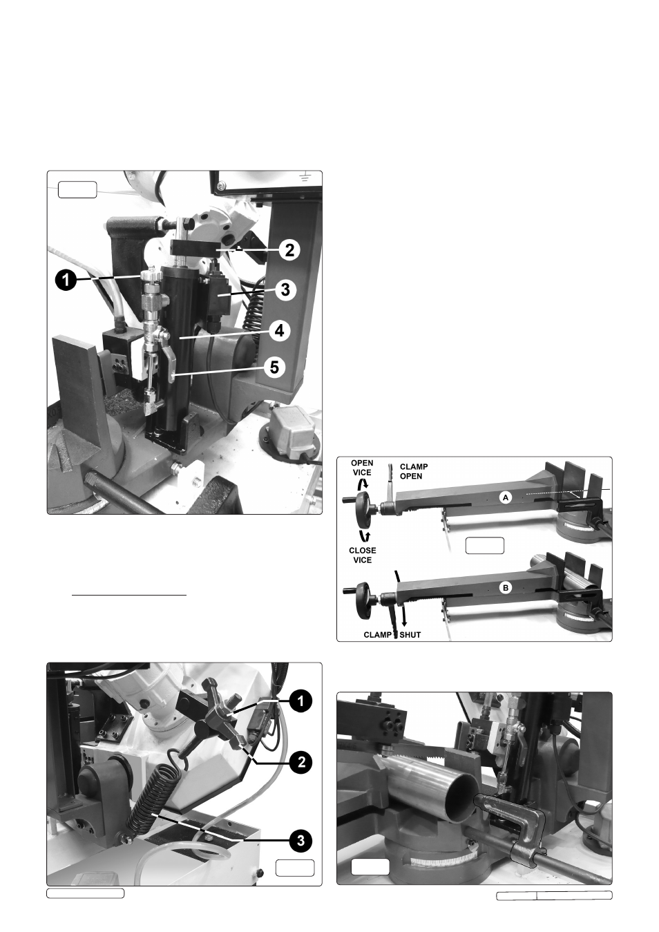
4.2.1 The rate of descent of the main cutting arm (bow) is controlled
by the cylinder (4) shown in Fig.5 below.
Fig.5
Fig.6
4.2.2 By turning the knob (1) clockwise the rate of descent is slowed
down. By turning the knob anticlockwise the rate of descent is
increased. The bow can be locked in any position by turning
the hydraulic flow off using the tap (5). When the tap is
at 90° to the cylinder the flow is off and the bow will stop
moving.
4.2.3
Automatic electric shut off. When the bow reaches its lowest
point the actuation arm (2) operates the microswitch (3) and
the power is shut off bringing the blade to a halt.
4.3 AJDUSTING BOW WEIGHT (See fig.6)
4.3.1 Bow weight is one of the most important adjustments on the
saw. Incorrect bow weight can result in poor performance.
4.4 VICE SET-UP AND ADJUSTMENT (See fig.7)
4.4.1 Adjust the vice opening to be larger than the material to be cut
using the hand wheel at the left hand side of the vice
assembly. Turn the handwheel clockwise to close the vice.
Turn
the hand wheel anticlockwise to open the vice.
4.4.2 Adjust the position of the stop bracket on the stop rod so that
the distance from the end of the bracket to the blade is the
same as the length of material to be cut as shown below in 'A'.
4.4.3 Lift the bow so that the blade is not passing through the vice
and lock the position with the tap on the hydraulic unit. Place
the metal stock to be cut into the vice so that it is up against
the stop bracket as shown below in 'B'. Close the vice to within
2mm of the material. Finally clamp the material in place by
sharply moving the clamp lever downwards (anticlockwise).
including rough or crooked cuts and premature dulling of the
blade. The hydraulic feed rate unit will not compensate for
improper bow weight. Bow weight is factory set and should not
normally require adjustment.
4.3.2 If performance problems are encountered adjust the bow
as follows:
4.3.3 Turn the hydraulic cylinder valve on and place the the saw arm
in the horizontal position.
4.3.4 Turn the feed rate valve at the top of the cylinder anticlockwise
until it stops.
4.3.5 Adjust the spring tensioner in Fig.6 to the required setting for
the stock being cut. Turn handle '2' clockwise to slow down the
rate of descent.
Fig.7
Fig.8
Original Language Version
SM354CE Issue: 3(SP) - 29/09/14
© Jack Sealey Limited