Fig. 6 fig. 7 – Sealey SM2502 User Manual
Page 5
4.4
Setting and locking the cutter height. once the workpiece is in place the rapid drill feed can be used to bring the cutter closer to
the workpiece but the final setting of the cutter height must be done with the fine feed wheel. to ensure accuracy during milling the
cutter height setting must then be locked by tightening the head lock lever. ( see fig.9 )
4.5
locking table travel. to eliminate the possibility of inadvertently moving one feed whilst operating the other you should lock the table
feed not being used. to lock the longitudinal table tighten the longitudinal feed lock lever on the front of the table ( See fig.3-10 ). to
lock the cross feed table tighten the cross feed lock lever to be found on the right hand side of the saddle. ( See fig.3-12 ).
4.6
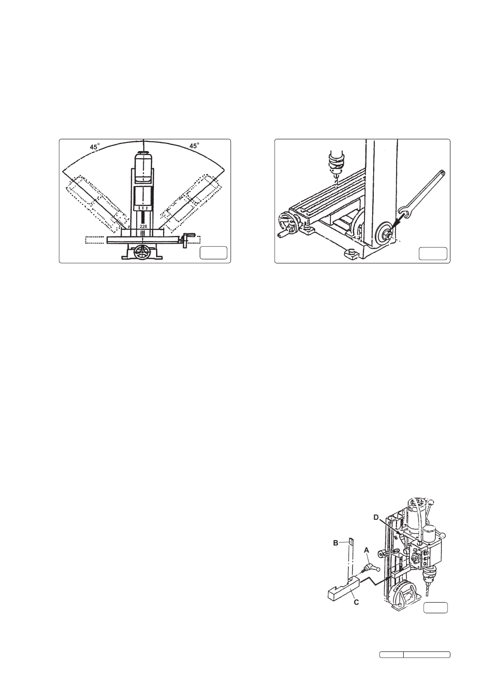
Setting the column angle. If required, the column carrying the head can be pivoted and locked at any angle between vertical and
45O in either direction as indicated in fig.6. Before loosening the pivot bolt ( See fig.7 ) the weight of the column must be firmly supported,
preferably by a second person. once the bolt is loose, lower the column to the required angle with reference to the scale provided
and fully tighten the bolt.
WARNINg. Support the column at all times during this procedure as once the pivot bolt is loose the head
could fall suddenly in either direction causing damage to the machine, associated equipment, or injury to persons.
fig. 6
fig. 7
4.7
Calibrated feed. each feed wheel has an adjustable calibration ring situated on the feed shaft immediately behind the wheel. the
rings can be rotated by hand to the desired mark.
4.7.1 the calibration rings for each of the three feeds are marked in increments of 0.025mm. there are 60 increments to one full
rotation of each feed wheel. one full rotation of a feed wheel will advance the cutter 1.5mm. each ring can be rotated allowing it to be
reset to zero or any mark required for a specific cut. the linear scales on the machine are marked in millimetres.
4.7.2 Avoid subjecting drills and cutting tools to excessive strain. do not apply undue force on the handle in order to cut the workpiece.
Maintain a controlled cutting speed through the workpiece.
4.8
Safety guard. After the workpiece has been fixed in place on the bed, but before switching on, ensure that the clear plastic guard
( See fig.3-8 ) is fixed in place.
4.9
Select high or low gear. the gear lever is situated on the left hand side of the head and selects either high or low gear.( see fig.8-d )
Select low gear (0 to 1100 rpm) by pushing the lever towards the back of the machine. Select high gear (0 to 2500 rpm) by pulling the
lever towards the front of the machine.
WARNINg! do not attempt to change gear whilst the machine is operating as this will
result in damage to the gearbox. Only change gear when the machine is at a complete standstill. As a general rule of thumb
harder materials will require a lower milling/drilling speed. the speed is infinitely variable within each gear and is controlled by the
rotary knob on the control box. See the next section for detailed operation of the speed control.
4.10
Main ON/OFF switch with speed control and emergency shut off. connect the machine to the mains power.
4.11
the rotary speed control must be set in the ‘I’ position otherwise the machine will not start. If it is not in this position rotate the knob
anticlockwise until it clicks and stops. ( see fig.3-6 )
4.12 release the emergency ‘off’ switch cover by pushing the large button upwards to release the latch on the yellow housing. ( fig.3-20 )
Hinge the cover upwards to reveal the red ‘off’ button for every day use. the green lamp under the rotary speed switch will now be
illuminated indicating that the machine can now be switched on. ( see fig.3-7 )
4.13 rotate the rotary speed switch slowly clockwise. As the knob is turned a click will be heard and the motor will start. As the knob is
turned further the speed will increase. Set the knob to the desired speed.
4.14
Stop modes. there are three ‘stop’ modes as described below.
(A). to stop the machine for a short while and then restart, simply return the rotary speed switch to the ‘I’ position. When you are
ready to restart, rotate the switch clockwise to the desired speed.
(B) When the yellow emergency stop cover is open the machine can be stopped by pressing the smaller red stop
button within the yellow housing. When this button is used an orange reset light will illuminate on the side of
the switch box. this
means that the rotary speed switch must be returned to the ‘I’ position before you can
restart the machine.
(c) In an emergency hit the large red emergency button which automatically shuts the
yellow cover and cuts the electrical supply to the machine. Before the machine will start
again the rotary speed switch must be returned to the ‘I’ position and the emergency
switch cover must be released by pushing the large red button upwards.
5.0
SeTTINg UP FOR dRIllINg.
( disconnect the machine from the power supply while setting up.)
5.1
engaging rapid drill feed. the rapid drill feed is controlled with the three rods emerging
from the hub on the right hand side of the head. ( See fig.3-2 ) the rapid drill feed will not
operate if the vertical fine feed wheel used for milling is still engaged. to make the rapid
drill feed operative take hold of the central hub and pull it outwards to disengage the
castellations on the hubs central shaft.
( See also fig.4 )
5.2
depth stop gauge. the depth stop gauge ( See fig.8-c ) consists of a lockable bar
which can be slid up and down the main column beneath the head. the depth stop can
be set in relation to the graduated scale attached to the side of the main column.
Alternatively, set the drilling depth using the rapid drill feed then move the depth stop up
to the head and lock it with the lever. ( see fig.8-A )
fig.8
Original Language Version
SM2502 Issue: 2 - 17/12/09