Fig. 1 fig. 2, Introduction & specification, Contents & assembly – Sealey SM2502 User Manual
Page 3
the SM2502 is a bench mounted mini drilling/milling machine with a variable speed drive giving flexibility to handle most materials. the table
has ‘t’ slots facilitating the securing of the work pieces. the machine is supplied with metric graduated compound scales. complies with
Machinery directive 98/37/ec and is fully ce approved. A 42 piece clamping kit is available as an optional extra, Model no.SM2502cK. the
machine is supplied with the accessories shown below. A stand is also available as an optional extra, Model no.SM3002St. (Milling attachments
and drill bits are not supplied.) for a full range of accessories see Section 8 or contact your local Sealey dealer.
2. INTROdUCTION & SPeCIFICATION
Spindle speed - low range . . . . . 0 to 1100 rpm + or - 10%
Spindle speed - High range . . . . . 0 to 2500 rpm + or - 10%
t - slot . . . . . . . . . . . . . . . . . . . . . . . . . . . . . . . . . . . . 12mm
Weight (net/gross) . . . . . . . . . . . . . . . . . . . . . . . . . . 50/68kg
Packing size . . . . . . . . . . . . . . . . . . . . . 560 x 500 x 740mm
Specification:
WARNINg! At least two people will be required to
move the machine. Observe good lifting practice.
3.1. unpack the product and check that all
components and tools are present and
undamaged. If any problem is noted contact your
supplier immediately.
3.2 the machine has been coated with heavy grease
to protect it in shipping. remove the coating with
commercial degreaser, kerosene or similar solvent
before operating. Avoid getting the solvent on
rubber parts. After degreasing coat the machined
surfaces with a medium consistency machine oil.
3.3 Mounting the machine. locate the machine on a
flat, level and strong work surface. do not locate
in direct sunlight or where heavy dust or moisture
is present.
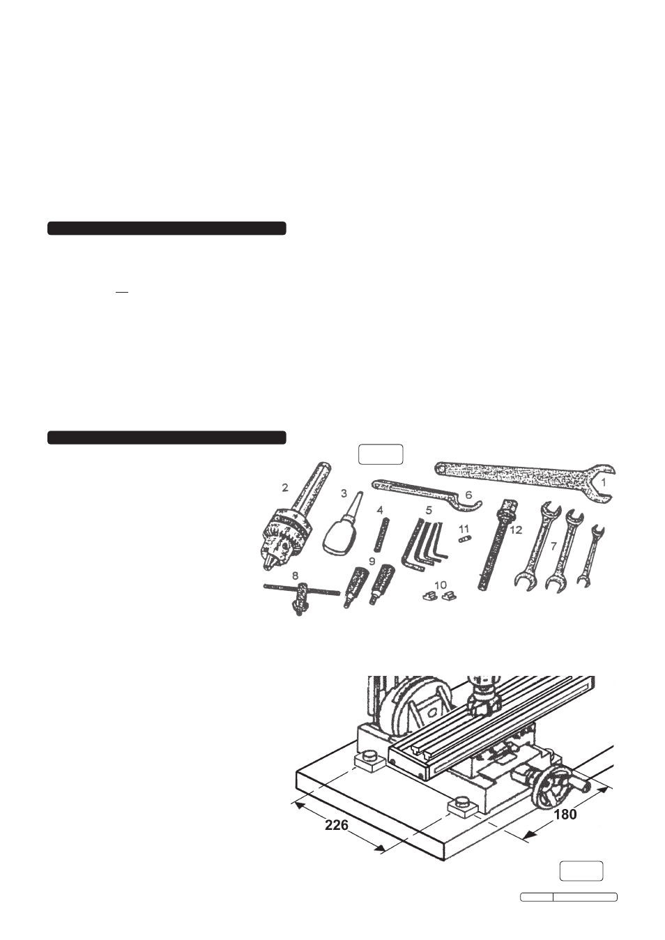
3.4 Before finalising the mounting position consider
the full extent of travel of the longitudinal table
leaving clearance for the operators hand. Also
consider access to the column pivot bolt and the
tilting of the column to 45
O in either direction.
drill the location holes in accordance with the
dimensions shown in fig.2 and bolt the machine to
the bench using four M10 nuts and bolts. ( not
provided.)
Contents / accessories description:(fig.1)
Mini drilling/milling machine.
1. large wrench
2. drill chuck and taper shank
3. oil can
4. locking pin
5. 4 Hex keys (3,4,5,6mm)
6. Socket head wrench
7. 3 double ended spanners 8-10,14-17,17-19
8. chuck key.
9. 2 Handles
10. ‘t’ nuts
11. fuse
12. draw bar
WARNINg! do not switch the drilling/milling machine on whilst the drill or cutting tool is in contact with the workpiece. Bring the drill or
cutting tool gradually to the workpiece. Avoid un-intentional starting of the drilling/milling machine.
do not force the drilling/milling machine to achieve a task it was not designed to perform.
do not allow untrained persons to operate the drilling/milling machine.
do not get the drilling/milling machine wet or use in damp or wet locations or areas where there is condensation.
WARNINg! do not use drilling/milling machine where there are flammable liquids, solids or gases such as petrol, paint solvents, waste
wiping rags etc.
do not operate the drilling/milling machine if any parts are missing or damaged as this may cause failure and/or possible personal injury.
do not remove the safety guard whilst in use.
do not attempt to remove a workpiece until the drill or cutting tool has stopped rotating.
do not touch the workpiece close to the cut as it will be very hot. Allow to cool.
do not leave the drill or cutting tool operating unattended.
do not operate the drill or cutting tool when you are tired or under the influence of alcohol, drugs or intoxicating medication.
When not in use switch the drilling/milling machine off and isolate from the power supply.
fig. 1
fig. 2
drilling capacity . . . . . . . . . . . . . . . . . . . . . . . . . . . . . 13mm
face Mill capacity. . . . . . . . . . . . . . . . . . . . . . . . . . . . 30mm
end Mill capacity . . . . . . . . . . . . . . . . . . . . . . . . . . . . 16mm
Headstock travel (Z). . . . . . . . . . . . . . . . . . . . . . . . . 180mm
cross axis (X). . . . . . . . . . . . . . . . . . . . . . . . . . . . . . 100mm
longitudinal axis (Y). . . . . . . . . . . . . . . . . . . . . . . . . 220mm
Spindle rotary angle . . . . . . . . . . . . . . . . . . . . . . -45° / +45
°
output power . . . . . . . . . . . . . . . . . . . . . . . . . . . . .350Watts
Spindle taper . . . . . . . . . . . . . . . . . . . . . . . . . . . . . . . . .Mt3
3. CONTeNTS & ASSeMBlY
Original Language Version
SM2502 Issue: 2 - 17/12/09