Fig.9 fig.11 7. drill speeds – Sealey GDM1630FR User Manual
Page 4
6.6.
Setting the drill depth
6.6.1.
Use the scale on the side of the drill head near the drill handle.
6.6.2.
Loosen locking screw (36) and set the scale to the depth required. Tighten locking screw.
6.6.3.
When ready to drill, simply pull the feed handle. The drill will stop at the set depth.
6.7.
Setting the drill head
6.7.1.
Fore and aft movement
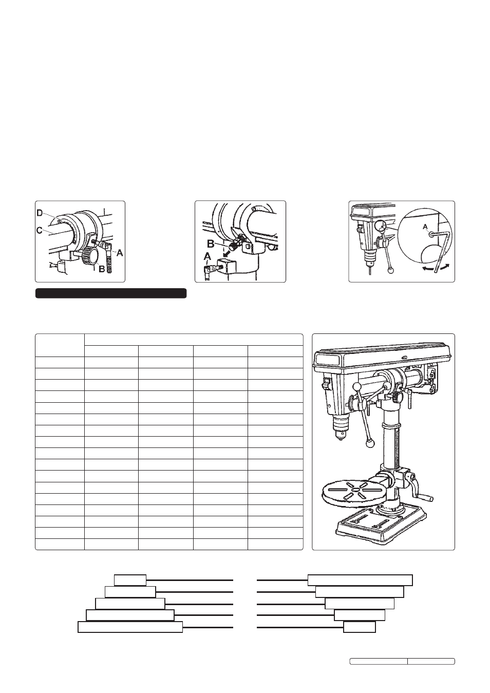
6.7.1.1. Loosen clamping lever (fig.9.A) and turn feed knob (fig.9.B) to move head to the required position. Retighten clamping lever.
6.7.2.
Horizontal rotation
6.7.2.1. Loosen clamping lever (fig.10.A) and rotate head on column to required position (360° rotation is available). Retighten clamping
lever.
6.7.3.
Tilting
6.7.3.1. Loosen clamping lever (fig.9.A), Pull out and turn - to hold out - vertical lock (fig.10.B). Head may now be tilted up to 45° clockwise
and 90° anticlockwise. Angular position is shown by line (fig.9.C) against scale (fig.9.D). When set, retighten clamping lever.
After returning head to the vertical position always re-engage the vertical lock.
6.7.4.
Head square to table
6.7.4.1. Confirm that head is in the ‘vertical’ position, that the vertical lock (fig.10.B) is engaged and that the clamping lever (fig.9.A) is tight.
6.7.4.2. Using a spirit level check that table is horizontal and, if necessary, adjust as in para.6.2.2.
6.7.4.3. Clamp a straight rod, or a drill bit, in the chuck and use a machinist’s square to check that the rod is perpendicular to the table.
Adjust drill head as necessary by loosening the two set screws (fig.11.A) either side of the spindle housing and rotating the housing
on the horizontal tube (81). When correctly positioned retighten set screws.
fig.9
fig.11
7. DRILL SPEEDS
The chart below shows recommended drill speeds for various bit diameters and materials. Select the available drill speed that is the
same as, or nearest to, the one recommended for the task in hand.
Drill Speed (rpm)
2450
1870
1330
790
500
Spindle Pulley
Motor Pulley
fig.10
Drill Diameter
(mm)
Drill Speed (rpm)
Steel
Cast Iron
Iron
Alum'& Copper
3
1820
2580
2580
2580
4
1350
1820
1820
2580
5
1290
1350
1350
2580
6
970
1290
1290
2580
7
830
970
970
2580
8
830
970
970
2580
9
500
970
830
1820
10
500
830
830
1820
11
500
830
830
1820
12
420
830
500
1820
13
420
500
500
1350
14
420
500
500
1350
16
320
500
500
1290
18
320
420
420
1290
20
280
320
320
970
22
210
320
280
970
25
120
280
210
830
Original Language Version
GDM790BR, GDM1630 Issue: 4 - 23/03/10