Operating instructions – Sealey GDM1630FR User Manual
Page 3
p
WArnIng! Ensure the drill is unplugged from the mains power supply before commencing.
6.1.
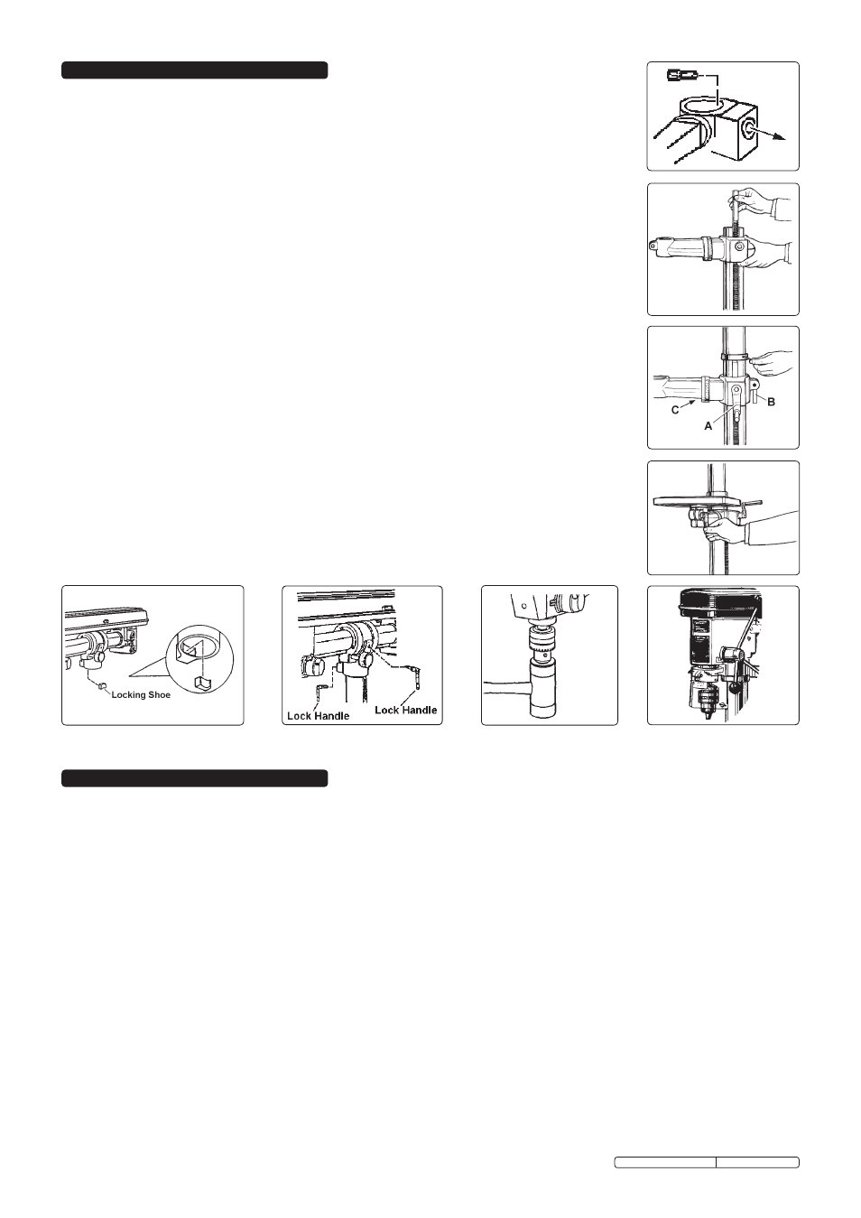
Installing drill bit
6.1.1.
Insert drill bit into chuck jaws to 1" (25mm) deep (avoid inserting small bits too far) and centre bit in chuck before tightening.
6.2.
Adjusting the table
6.2.1.
To adjust table up or down, loosen lock handle (fig.3.B) then turn bracket handle (fig.3.A). Once at correct height tighten lock handle
(fig.3.B).
6.2.2.
To adjust table tilt, loosen the work table bolt (fig.3.C), adjust table to the desired angle, then retighten bolt.
6.2.3.
To turn the table around the column, loosen the rack collar slightly, then loosen the lock handle (fig.3.B).
Turn the table to the desired position then secure the lock handle and rack collar.
6.3.
Adjusting the speed
6.3.1.
Open the pulley cover (48) and loosen the motor adjustment screw (36).
6.3.2.
Choose the speed for the drilling operation (see drill speed chart - Section 7) and move the belt to the correct pulley grooves
for that speed, as shown on the pulley chart - Section 7.
6.4.
Belt tension
6.4.1.
With the motor adjustment clamp screw (36) loose and using hand pressure on the motor, set tension so that belt give is no more
than 10mm each side, at centre span, under finger pressure. Tighten clamp screw (36).
6.5.
Positioning the workpiece
6.5.1.
Rest the workpiece on a piece of wood to to prevent the drill bit damaging the table when it breaks through the workpiece. The wood
should rest on the table so that one end of it is against the left side of the column. This will prevent the wood spinning when the drill
bit breaks through into it.
6.5.2.
For small workpieces that cannot be clamped to the table, use a drill vice (not included). Vice must be bolted to table.
6. OPERATING INSTRUCTIONS
Notes: 1) Diagrams are illustrative and may differ in detail from your drill.
2) Numbers in brackets refer to item numbers in the Parts List and Diagram
5.1. Assembly
5.1.1. Place the column (4) on the base (2), align holes and secure with the bolts (5) provided.
5.1.2. Insert worm gear (9) into table bracket, meshing it with the lift gear (7) (fig.1).
5.1.3. Fit table bracket (6) onto column (4) together with rack (15) (fig.2), engaging gear (7) in bracket with rack.
5.1.4. Install the rack collar (93) and tighten set screw (94) firmly (fig.3).
5.1.5. Fit the table adjusting handle (10) (fig.3.A) and lock handle (14) (fig.3.B).
5.1.6. Tighten the adjusting handle set screw (11) onto the flat on the worm gear shaft (9).
5.1.7. Install the table (16) and table lock handle (14) (fig.4).
5.1.8. Ensure that the column head assembly (83) is approximately midway between the motor (69) and
the spindle housing (25) and then insert locking shoe (88) into column head (84) (fig.5).
5.1.9. Place the head assembly over the column (4) and slide column head (84) down onto column.
Tighten lock handles (fig.6)
p
WArnIng! If the column head assembly is not positioned midway there is a risk that
the whole drill assembly may become unstable when the head assembly is fitted.
5.1.10. Screw the three feed handles and knobs (37/38) into the hub (35) of the pinion shaft.
5.1.11. To install chuck (46) open the chuck jaws completely by turning the chuck key (46A) counter-clockwise.
Hold chuck on spindle and tap into place on taper with a hammer (fig.7).
5.1.12. Loosen clamp screw on safety guard mounting collar, pass guard up over chuck and fit collar round
flange of quill (40). Ensure guard pivot is central and tighten clamp screw (see fig.8).
5.1.13. Open pulley cover (48), loosen butterfly set screw (36) on motor adjustment and fit belt (73) to pulleys
(19/79). Pull motor (69) back to tension belt and retighten screw (36).
5.2.
Drill mounting
p
WArnIng! For stability and safety it is imperative that the drill base is securely bolted to the
workbench (gDM790br) or floor (gDM1630Fr).
5.2.1. Ensure that the mounting surface is capable of supporting the drill together with the weight of the
heaviest likely workpiece.
5. ASSEMBLY
fig.2
fig.3
fig.4
fig.1
fig.6
fig.8
fig.7
fig.5
Original Language Version
GDM790BR, GDM1630 Issue: 4 - 23/03/10