Fig.3 fig.2, Fig.5, Fig.4 – Sealey SG101 User Manual
Page 3: Assembly & adjustment
WARNING! Ensure that the grinder is unplugged from the power supply before assembly.
3.1.
Fitting the Guard Assembly. (SG101.V2)
3.1.1 The guard may be orientated at any angle to suit the grinding task required and should be positioned to allow maximum working
performance whilst providing maximum personal protection for the operator.
3.1.2 Loosen locking screw and turn the guard to the required position. Lock the guard in place by re-tightening the locking screw.
3.2.
Fitting the Guard Assembly. (SG115.V2, SG125)
3.2.1 The guard may be orientated at any angle to suit the grinding task required and should be positioned to allow maximum working
performance whilst providing maximum personal protection for the operator.
3.2.2 Take the guard and place it around the spindle as in fig.4, place the securing plate (fig.4B) around the spindle and line up the
holes in the plate with the holes in the main unit as in fig.4 and secure with screws (fig.4A).
3.3
Fitting the Guard Assembly. (SG2303.V2)
3.3.1 The guard may be orientated at any angle to suit the grinding task required and should be positioned to allow maximum working
performance whilst providing maximum personal protection for the operator.
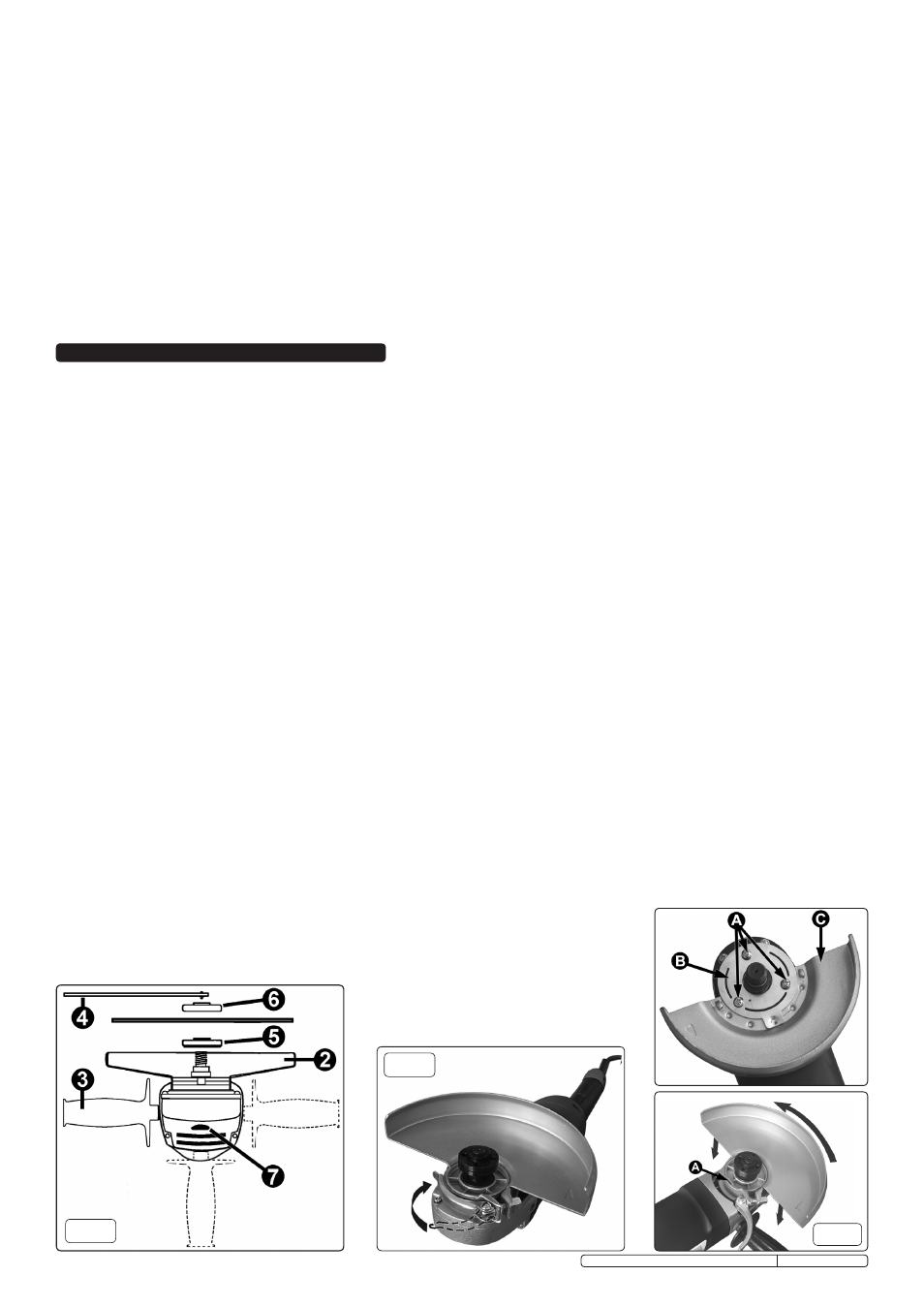
3.3.2 Take the guard (fig.1 item 2) and unlock the clamp. On the inside of the guard clamping collar is a small pip (indicated by arrow ‘A’ in fig.5)
which must be aligned with a notch in the housing (also indicated by arrow ‘A’). Orientate the guard as shown in fig.5 and place it over the
central spindle and onto the housing. Leaving the clamp open, rotate the guard on the housing until it is over the main body of the tool as
indicated in fig.3.
3.3.3 Lock the guard in place by pushing the clamp lever towards the centre spindle as shown in fig.3.
3.4
Attaching a Grinding/Cutting Disc.
(Discs should only be fitted by a person holding a grinding wheel certificate).
3.4.1 Lay the grinder on it’s back and place the clamping flange onto the centre spindle with the
raised ring facing upwards (see fig.2 item 5). Rotate the clamping flange on the spindle until the flats on its back face drop into alignment
with the flats on the spindle. When the clamping flange is in the correct position it can no longer be rotated on the spindle.
3.4.2 Place the grinding (or cutting) disc over the spindle and onto the clamping flange.
Figures A, B & C show the correct orientation of the disc retaining flange nut for the different types of disc.
(SEE OVER)
3.4.3 When using a grinding disc with a depressed centre portion as in fig.A, Screw the disc retaining flange nut onto the spindle with the raised
ring facing downwards.
3.4.4 When using flat cutting discs as in fig.C and cutting discs with a depressed centre portion as in fig.B, screw the disc retaining flange nut
onto the spindle with the raised ring facing upwards.
3.4.5 Stop the spindle from turning by pushing in and holding the disc stop button (see fig.2.7).
3.4.6 Lock the grinding disc into place by tightening the disc retaining flange nut with the pin wrench (fig.2 item 4).
3.4.7 When complete, release the locking button and check that it has sprung back to its initial position.
3.5
Fitting the Hand Grip.
Always use the hand grip for better control and improved safety. Fit the hand grip (fig.1.3 ) by screwing it into the
appropriate left, right or top position on the grinder head as indicated in fig.2.
3. ASSEMBLY & ADJUSTMENT
fig.3
fig.2
SPECIFICATION - SG101.V2
Power input . . . . . . . . . . . . . . . . . . . . 600 watt
No-load speed . . . . . . . . . . . . . . . . 11,000rpm
Spindle size . . . . . . . . . . . . . . . . . . . . . . . M10
Grinding/Cutting disc max. diam . . . . .100mm
Sound pressure level . . . . . . . . . . . .85.1dB(A)
Sound power level . . . . . . . . . . . . .96.19dB(A)
Weight . . . . . . . . . . . . . . . . . . . . . . . . . . 1.8kg
SPECIFICATION - SG115.V2
Power input . . . . . . . . . . . . . . . . . . . . 900 watt
No-load speed . . . . . . . . . . . . . . . . 11,000rpm
Spindle size . . . . . . . . . . . . . . . . . . . . . . . M14
Grinding/Cutting disc max. diam . . . . . 115mm
Sound pressure level . . . . . . . . . . . . 86.3dB(A)
Sound power level . . . . . . . . . . . . . . 99.3dB(A)
Weight . . . . . . . . . . . . . . . . . . . . . . . . . . .2.2kg
SPECIFICATION - SG2303.V2
Power input . . . . . . . . . . . . . . . . . . . 2000 watt
No-load speed . . . . . . . . . . . . . . . . . 6,000rpm
Spindle size . . . . . . . . . . . . . . . . . . . . . . . M14
Grinding/Cutting disc max. diam . . . . . 230mm
Sound pressure level . . . . . . . . . . . . 91.2dB(A)
Sound power level . . . . . . . . . . . . . 104.2dB(A)
Weight . . . . . . . . . . . . . . . . . . . . . . . . . . .5.5kg
SPECIFICATION - SG125
Power input . . . . . . . . . . . . . . . . . . .1000 watt
No-load speed . . . . . . . . . . . . . . . . 11,000rpm
Spindle size . . . . . . . . . . . . . . . . . . . . . . . M14
Grinding/Cutting disc max. diam . . . . . 125mm
Sound pressure level . . . . . . . . . . . . 89.4dB(A)
Sound power level . . . . . . . . . . . . . 102.4dB(A)
Weight . . . . . . . . . . . . . . . . . . . . . . . . . . .2.4kg
fig.4
fig.5
Original Language Version
SG101.V2, SG115.V2, SG125, SG2303.V2 Issue: 2 - 16/02/10