20mm 3 - 8mm, Ab c d, Fig. 12 – Sealey TS12CZ User Manual
Page 5: Fig. 13 fig. 14
6. SETTING BLADE ANGLE & HEIGHT
7. OPERATING THE SAW
fig. 10
fig. 11
20mm
3 - 8mm
6.1
Adjusting the blade angle. to adjust the angle of the
blade, loosen the two clamp knobs to be found at either
end of the motor/blade box close to the underside of
the table. (see fig.12-A).
6.1.1 take hold of the bottom of the motor/blade box and
move it to the required angle which can be read off
the scale adjacent to the knob. (see fig.12-B).
6.1.2 When the required angle has been set tighten the
clamp knobs at both ends of the box.
6.2
Adjusting the depth of cut/blade height. to adjust
the height of the blade, use the winding handle
mounted on one end of the motor/blade box as shown
in fig.12-D. the depth of cut can be read from the
adjacent pointer and scale. (see fig.12-c). Wind the
handle clockwise to raise the blade and anti-clockwise
to lower it.
fig. 12
A
B
C
D
WARNING! As with all power tools, there are potential hazards involved in
the use of this saw. It is, therefore, vital to ensure you have read and
understood all the safety instructions in Section 1. familiarise yourself
again with the specific saw safety rules for each step of the following
operation. failure to do so could cause serious damage and/or personal
injury and may invalidate your warranty. Disconnect the saw from the
mains power before making any adjustments or removing/fitting the blade.
Ensure that all screws and nuts are secure and that the blade is in good
condition and correctly fitted.
Wear approved safety eye and respiratory protection.
WARNING! Wood dust can be harmful to health by inhalation and skin contact
and concentrations of small dust particles in the air can form an explosive
mixture. Therefore, ensure that there is adequate ventilation and that the saw
is attached to a dust-extraction unit.
7.1.
Cross cutting
7.1.1 When cross cutting, the fence assembly is mounted to the sliding guide on
the side of the table and will slide within the guide (fig.14). for angled cuts
loosen the large black knob on the angle plate and set the required angle
using the scale provided. firmly tighten the black knob.
7.1.2 Adjust the side to side positioning of the fence bar so that as the workpiece is
moved towards the blade the bar is out of the line of cut and will not make
contact with any part of the blade guide.
7.1.3 If a bevelled cut is required set the blade angle as described above.
7.1.4. When the cross cut has been completed, the waste off-cut will be
unsupported and will either remain on the saw table or fall off. Before starting,
therefore, consider how you will handle the off-cut.
7.1.5. check that everything is ready and that the blade guard is fully down.
Plug the saw into the mains power supply and switch the saw on.
7.1.6. Hold workpiece firmly against the guide assembly and table as shown in fig.13
7.1.7. slowly move the workpiece forward into the rotating blade. continue holding
the workpiece firmly whilst passing it completely past the blade so that it is cut into two.
7.1.8. Before drawing the workpiece back towards yourself, move it slightly to the side so that it is clear of the saw blade.
7.1.9 switch the machine off.
WARNING! DO NOT attempt to pick up an off-cut before the saw blade has stopped completely
WARNING! DO NOT use the fence as a cut-off gauge when cross-cutting.
fig. 13
fig. 14
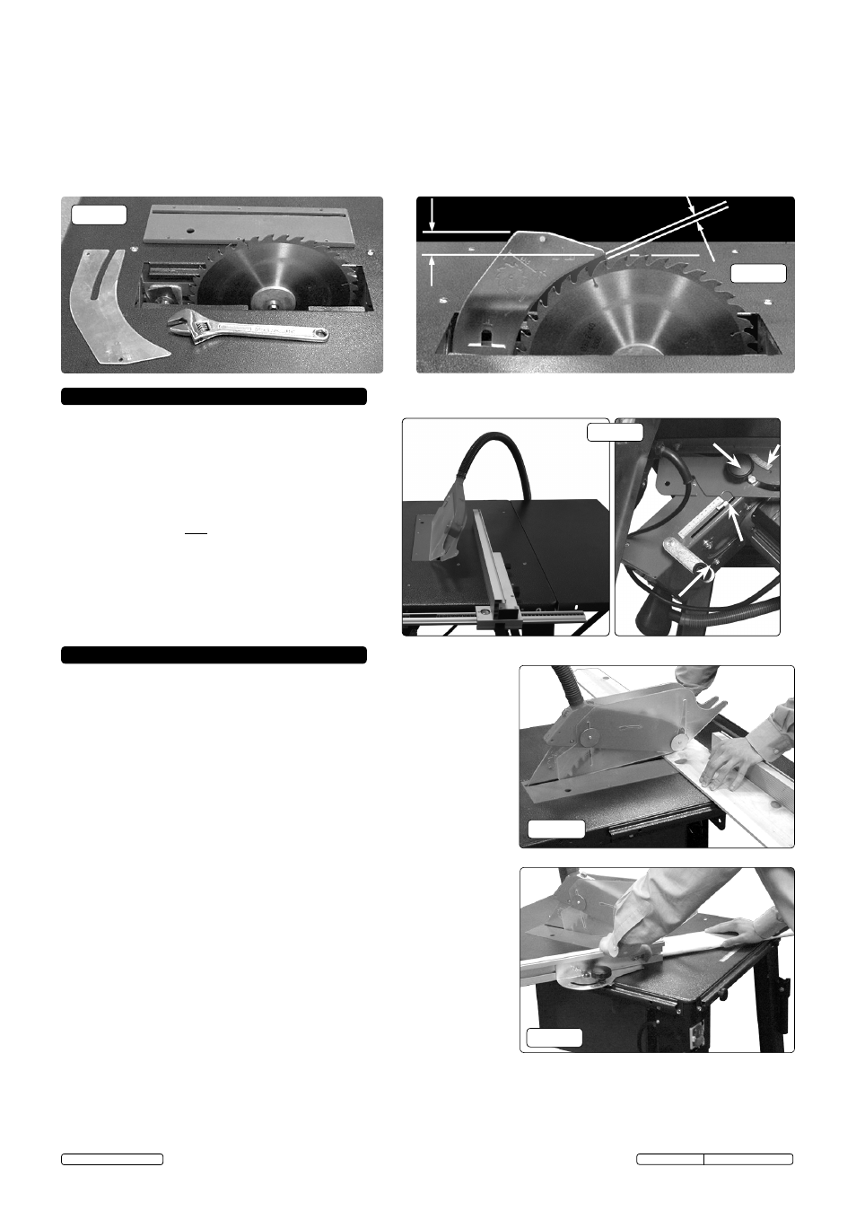
5.3.
Fitting the riving knife.
5.3.1. to fit the riving knife (shown in fig.10) firstly loosen the riving knife clamp then slide the slotted end of the riving knife between
the two halves of the clamp and move it downwards into the position shown in fig.11.
5.3.2 the position of the knife can be adjusted by moving it up or down and/or sliding the whole clamp towards or away from the blade.
Adjust the position according to the dimensions in fig.11 then firmly tighten the clamp nut.
5.4.
Fitting the blade guard. the blade guard assembly should be attached to the riving knife using the M6 x 25 bolt and lock nut
provided. Do not overtighten. the guard should be free to hinge up and down as different thickness of wood pass underneath it.
5.4.1 Attach the dust extraction pipe to the outlet on the blade guide. Attach the other end to the dust extraction duct mounted on the
blade/motor box. slide the loose centre portion of the pipe into the bracket attached to leg 6.
Original Language Version
ts12cZ.V2 Issue: 3 (1)- 23/08/13
© Jack sealey Limited