Fig.1 fig.2 – Sealey IR3000 User Manual
Page 2
3.1
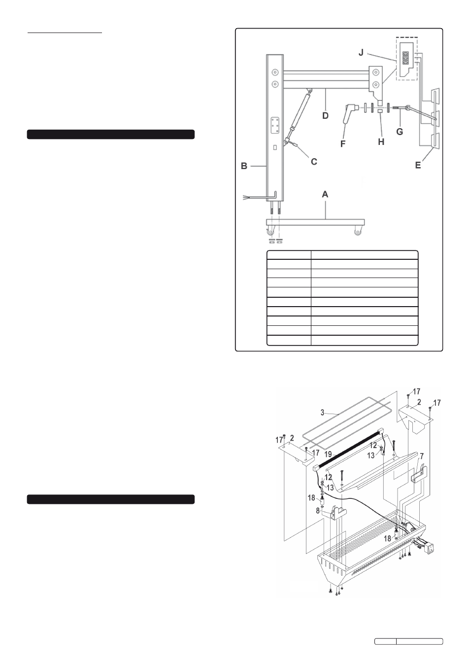
Assemble unit (fig.1).
3.1.1 unpack u shape base (A) place on floor and lock rear wheels.
3.1.2 unpack main upright (B) remove nuts and washers from the
base of the upright.
Caution! do not remove safety strap.
3.1.3 Place protruding bolts on upright into pre-drilled holes in base.
lightly hold in place with washers and nuts. cut and remove
safety strap, tighten nuts and secure being careful not to touch
the gas strut handle.
3.1.4 raise support arm (d) carefully using handle (c) on gas strut
until the arm is horizontal to main upright. ensure support arm
is being held whilst being raised.
3.1.5 unpack cassette module (e) and remove locking handle (f) and
special washers.
3.1.6 Place star washer onto protruding cassette bolt (G), then fit bolt
into hole on swivel head (H). then place the star washer, plain
washer and secure with the handle.
3.1.7 Plug cassette cables into socket (J).
3.1.8 the unit may now be operated by pushing the handle (c) on
the lockable gas strut while pulling down or pushing up the
support arm (d) to the desired position.
3.1.9 Ir3000 is
not supplied with fitted a plug. there are three options:
• 230V 13A uK Bs approved plug
• Blue Industrial IP44 2pin + earth plug
• Have the unit hard-wired.
Important: If in any doubt, contact a qualified electrician.
3.2
Lamp replacement (fig.2). (the Ir3000 is supplied with the
lamps fitted, follow the procedure below when replacement
lamps are required)
3.2.1. ensure the power supply is disconnected. remove the two screws (17) from
one end reflector (2), this will release the guard (3) and expose one of the
lamp terminal end posts (18).
3.2.2. now remove the other end reflector (2) exposing the other lamp terminal (18).
3.2.3. release the nuts (12) on the exposed terminal end posts just enough to allow
the fork terminals of the lamp leads to be pushed under the washers (13).
3.2.4. carefully remove the lamp (19) from its packing, holding it by the porcelain
end caps only, taking care not to handle the quartz glass.
3.2.5. carefully insert the end caps of the lamp under the spring retaining clips
(7 & 8) of the heater. the fork terminals on each end of the lamp should now
be inserted under the washer(13) of the lamp end posts and nuts (12)
tightened to make a good connection.
3.2.6. the lamp leads should then be tucked away around the space at each end of
the heater.
3.2.7. now replace the end reflectors (2) and guard (3) to complete the assembly.
Product features include
•
500mm 1kW High output short wave tubes.
•
Long lamp life with an average of 6000hours.
•
Specially designed electronic power and time control, offering
0 - 100% heat instantly through twin 30 minute timers on both
the flash and Bake settings.
•
Robust steel constructed stable frame, fitted with rear wheel
locking castors.
•
Maintenance free cassettes with no fan or filter changes.
•
Easy height adjustment by locking gas strut.
•
Individually switched cassettes.
•
Horizontal or vertical cassette operation.
4. oPErAtion
3. AssEMBLY
Note: The IR lamps are fragile and therefore it is important that the IR3000 is
not subjected to any unnecessary shocks or vibration and is not moved
when the lamps are on.
WArninG! Ensure that you read, understand and apply the safety
instructions in Section 1 before using the panel dryer.
Your Ir3000 Panel dryer can be used successfully on filler, Primer and finish coats
BEforE UsE: check our Paint data Guide for appropriate drying times. If applicable
we recommend you contact your own paint supplier with regard to short wave infrared
drying of paints and colours not listed in our guide.
4.1.
move the Ir3000 into position, approximately 500mm (20 inches) from the
area to be heated. Adjust the cassette heads around the contours of the
repaired area and lock into position.
4.2. switch on main isolator, set flAsH and BAKe controls to desired time and
temperature settings. the Ir3000 incorporates an electronic system which
allows fully variable heat control on both the flAsH and BAKe cycle.
itEM
CoMPonEnts
A
BAse
B
mAIn uPrIGHt
c
GAs strut HAndle
d
suPPort Arm
e
cAssette module
f
locKInG HAndle
G
cAssette Bolt
H
sWIVel HeAd
J
socKet
fig.1
fig.2
Original Language Version
Ir3000 Issue: 2 - 14/04/10