Fig.4, Fig.3, Fig.5 – Sealey DFS55 User Manual
Page 3: Control panel, Air supply 6. preparation & connections
6.1
Connecting an Air operated tool.
IMPORTANT: See section 4 for details of external air
supply system.
6.1.1 fIT THE fINE PARTICLE fILTER. (fig.2C) undo the clasps
that hold the power head onto the drum (see fig.1-12) and lift
off the head. Remove the cartridge filter if fitted and drop the
large fine dust filter into the drum so that it rests on the rim of
the container. Replace the power head and secure it with the
clasps.
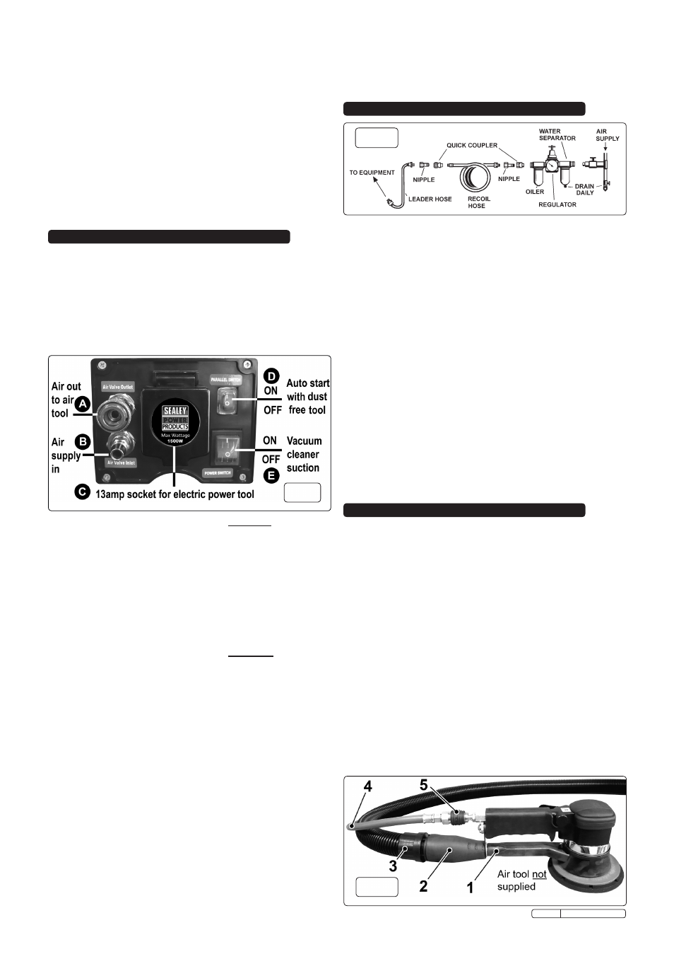
6.1.2 TRIM RuBBER ADAPTOR. Take the dust free rubber
adaptor (see fig.5-2) and trim the coned end with a sharp
knife so that it is a tight fit onto the dust extraction port on the
air tool (see fig.5-1).
6.1.3 CONNECT fLEXIBLE HOsE. Insert the smaller end of the
flexible hose fully into the rubber adaptor (see fig.5-3). Insert
the larger end of the flexible hose into the suction port
on the front of the drum (see fig.1-5).
6.1.4 CONNECT AIR LINE TO AIR TOOL. Connect an air line to
the coupling on the air tool (see fig.5-5). Connect the other
end of the air line to the air output coupling on the control
panel. (see fig.3-A)
6.1.5 sET uP sWITCHEs fOR DusT fREE OPERATION. see
section 4.2.
fig.4
Accessories. Refer to fig.2.
A.
Cartridge filter. use for wet or dry vacuuming. filter must be
dry before commencing dry vacuuming.
B.
dust collection bag. use for dry vacuuming only. Replace
bag when full.
C.
Fine dust particle filter. use for dry vacuuming of fine dust
when unit is being used with a dust free tool.
d.
Flexible suction hose. use for both wet and dry vacuuming.
E.
Brush accessory. use for dry vacuuming only.
F.
Floor tool with brush. use for dry vacuuming only.
G.
Floor tool with flexible rubber skirt. use for wet vacuuming.
H.
dust free rubber adaptor. Connects the flexible hose
(suction) to a dust free tool port. Trim adaptor to fit.
I.
Crevice tool. use for both wet and dry vacuuming.
J.
Bent connector tube. use to connect extension tubes to hose.
K.
Extension tube. use for both wet and dry vacuuming.
4. CONTROL PANEL
4.1
WET OR dRY VACUUMING ONLY.
4.1.1 To use the unit as a standard wet or dry vacuum cleaner
without a dust free tool attached the Parallel switch (auto
start), see fig.3D, must be in the Off position. Press the
lower part of the switch ("O") to turn it off.
4.1.2 Press the upper part ("I") of the Vacuum on/off switch (see
fig.3E) to start the vacuum cleaner.
NOTE: The main on/off switch will not work if the Auto Start
switch is left on.
4.2
VACUUMING WITH A dUST FREE AIR TOOL ATTACHEd.
4.2.1 To use the unit with a dust free air tool attached the Parallel
switch (auto start), (see fig.3D), must be in the ON position.
Press the upper part of the switch ("I") to turn it on.
4.2.2 The main Vacuum on/off switch (see fig.3E) must also be in
the ON position. Press the upper part ("I") of the switch.
NOTE: The unit will not start until the air tool is activated.
4.2.3 When the air tool is switched on a sensor within the unit will
automatically switch on the vacuum.
4.2.4 When the air tool is switched off the vacuum will continue to
run for 10 seconds to clear any dust left in the system and
then shut down.
4.3
VACUUMING WITH A dUST FREE ELECTRIC TOOL .
4.3.1 To use the unit with a dust free electric tool attached the
Parallel switch (auto start), (see fig.3D), must be in the ON
position. Press the upper part of the switch ("I") to turn it on.
4.3.2 The main Vacuum on/off switch (see fig.3E) must also be in
the ON position. Press the upper part ("I") of the switch.
NOTE: The unit will not start until the electric tool is activated.
4.3.3 When the electric tool is switched on a sensor within the unit
will automatically switch on the vacuum.
4.3.4 When the air tool is switched off the vacuum will continue to
run for 10 seconds to clear any dust left in the system and
then shut down.
4.4
INdEPENdENT USE OF TOOLS .
4.4.1 Once the vacuum cleaner is plugged into the power supply
the 13amp socket in the centre of the control panel becomes
live. Any electric tool plugged into it can be used independently
without having to switch the unit on.
4.4.2 similarly, when an air supply is attached to the control panel
an air tool can be run from the air output without having to
switch on the vacuum.
4.5
dUAL USAGE OF TOOLS .
4.5.1 When a dust free air tool is in use with the vacuum running
an electric tool such as a drill can be operated from the
13amp socket.
4.5.2 similarly, when an electric dust free tool is in use with the
vacuum running an air tool such as a drill can be operated
from the air output on the control panel.
NOTE: Only one dust free tool can operate at any one time.
fig.3
The recommended hook-up is shown in fig.4.
WARNING! Ensure correct air pressure is used, maintained,
and not exceeded for the appropriate sander attachment.
5.1
In order to provide 10.6cfm free air delivery to the sanding
tool there should be a minimum of 13cfm free air delivered to
the air inlet of the dust free vacuum system. We recommend
the use of a 3hp (or more) compressor.
5.2
Ensure the air valve on the supply is in the "off" position
before connecting to the air inlet on the unit.
WARNING! Ensure the air supply does not exceed 90psi
while operating the sander. Too high an air pressure and
unclean air will shorten the product life due to excessive
wear and may be dangerous, causing possible damage and
personal injury.
5.3
Drain the air tank daily. Water in the air line will damage the tool.
5.4
Clean the air inlet filter screen weekly.
5.5
Line pressure should be increased to compensate for
unusually long air hoses (over 8 metres).
5.6
Air supply must be delivered through a 3/8” internal diameter
air hose. If you use a 5/16” internal diameter the performance
of the tool may suffer. fittings must have the same inside
dimensions.
5.7
Keep hose away from heat, oil and sharp edges. Check
hoses for wear, and make certain that all connections are
secure.
5. AIR SUPPLY
6. PREPARATION & CONNECTIONS
fig.5
Original Language Version
Dfs55 Issue: 2 - 17/02/10