Assembly – Florabest FBKS 4015 User Manual
Page 7
GR
58
Πρüβληmα
Αιτßα
Λýση
Η mηχανÞ δεν
ξεκινÜ.
1. ∆ιακüπιη ΟΝ/
STOP στη θÝοη
STOP.
2. Η mηχανÞ εßναι υπερπληρωmÝνη.
3. Η δεξαmενÞ καυσßmων εßναι
Üδεια.
4. Ο αναφλεκτÞραj δεν ανÜβει.
5. Τα καýσιmα δεν φτÜνουν στο
καρmπυρατÝρ.
1. ΜετακινÞστε το διακüπιη ΟΝ/
STOP
στη θÝοη ΟΝ.
2. ∆εßτε «Ο∆ΗΓΙΕΣ ΕΚΚΙΝΗΣΗΣ».
3. Γεmßστε τη δεξαmενÞ mε το σωστü
mεßγmα καυσßmων.
4. ΤοποθετÞστε Ýναν καινοýργιο
αναφλεκτÞρα.
5. ΕλÝγξτε το φßλτρο καυσßmων και
αλλÜξτε το αν εßναι βρþmικο.
ΕλÝγξτε το σωληνÜκι καυσßmων
και αν διαπιστωθεß στρÝβλωση Þ
σχßσιmο, επιδιορθþστε Þ ανταλλÜξτε
το σωληνÜκι.
Η mηχανÞ
δεν mπαßνει
στη νεκρÜ
θÝση.
1. Η ταχýτητα ρελαντß χρειÜζεται
ρýθmιση.
2. Το καρmπυρατÝρ χρειÜζεται
ρýθmιση.
1. ∆εßτε “Ρýθmιση ΚαρmπιρατÝρ” στην
Ενüτητα ΣυντÞρησηj και Ρυθmßσεων.
2. ΕπικοινωνÞστε mε Ýναν εξουσιοδ—
οτηmÝνο αντιπρüσωπο σþλησηj και
συντÞρησηj.
1. Το φßλτρο αÝροj εßναι
βρþmικο.
2. Ο αναφλεκτÞπαj εßναι
ρυπαρüj.
3. 'Εχει τεθεß σε λειτουργßα το
αλυσüφρενο.
4. Το καρmπυρατÝρ χρειÜζεται
ρýθmιση.
Η mηχανÞ δεν
επιταχýνεται,
Ýχει
mειωmÝνη
ισχý, Þ σβÞνει
üταν
φορτþνεται.
1. Καθαρßστε Þ αλλÜξτε το φßλτρο αÝροj.
2. Καθαρßστε Þ αλλÜξτε τον αναφλ—
εκτÞρα και επαναριθυεßστε το
διÜκενü του.
3. Ελευθερþστε το αλυσüφρενο.
4. ΕπικοινωνÞστε mε Ýναν εξουσιοδ—
οτηmÝνο αντιπρüσωπο σþλησηj και
συντÞρησηj.
Βγαßνει
υπερβολικü
j καπνüj
απü τη
mηχανÞ.
1. ΑδειÜστε τη δεξαmενÞ καυσßmων και
ξαναγεmßστε την mε το κατÜλληλο
mεßγmα καυσßmων.
1. Το mεßγmα των καυσßmων δεν
εßναι το κατÜλληλο mεßγmα.
ΠΙΝΑΚΑΣ ΕΠΙΛΥΣΗΣ ΠΡΟΒΛΗΜΑΤΩΝ
ΠΡΟΕΙ∆ΟΠΟΙΗΣΗ:
ΑποσυνδÝστε το mπουζß πριν κÜνετε συντÞρηση, εκτüj
απü τη ρýθmιση του καρmπυρατÝρ.
Η αλυσßδα
κινεßται
στην
ταχýτητα
ρελαντß.
1. Η ταχýτητα ρελαντß χρειÜζεται
ρýθmιση.
2. Ο συmλÝκτηj χρειÜζεται
επιδιüρθωση.
1. ∆εßτε “Ρýθmιση ΚαρmπιρατÝρ” στην
Ενüτητα ΣυντÞρησηj και Ρυθmßσεων.
2. ΕπικοινωνÞστε mε Ýναν εξουσιοδ—
οτηmÝνο αντιπρüσωπο σþλησηj και
συντÞρησηj.
GB
7
KICKBACK SAFETY FEATURES
WARNING
: The following features are
included on your saw to help reduce the hazard
of kickback; however, such features will not to-
tally eliminate this dangerous reaction. As a
chain saw user, do not rely only on safety de-
vices. You must follow all safety precautions,
instructions, and maintenance in this manual to
help avoid kickback and other forces which
can result in serious injury.
S
Reduced--Kickback Guide Bar, designed
with a small radius tip which reduces the size
of the kickback danger zone on the bar tip. A
Reduced--Kickback Guide Bar has been
demonstrated to significantly reduce the
number and seriousness of kickbacks.
Small Radius Tip
Reduced Kickback
Symmetrical
Guide Bar
Symmetrical Guide Bar
Large Radius Tip
S
Low--Kickback Chain, designed with a
contoured depth gauge and guard link
which deflect kickback force and allow
wood to gradually ride into the cutter.
Low-Kickback Chain
Contoured Depth Gauge
Elongated Guard Link
Deflects Kickback
Force And Allows
Wood To Gradually
Ride Into Cutter
S
Handguard, designed to reduce the
chance of your left hand contacting the
chain if your hand slips off the front handle-
bar.
S
Position of front and rear handlebars, de-
signed with distance between handles and
“in-line” with each other. The spread and
“in-line” position of the hands provided by
this design work together to give balance
and resistance in controlling the pivot of
the saw back toward the operator if kick-
back occurs.
WARNING
: DO NOT RELY UPON
ANY OF THE DEVICES BUILT INTO YOUR
SAW.
YOU SHOULD USE THE SAW
PROPERLY AND CAREFULLY TO AVOID
KICKBACK. Reduced--kickback guide bars
and low--kickback saw chains reduce the
chance and magnitude of kickback and are
recommended. Your saw has a low kickback
chain and bar as original equipment. Re-
pairs on a chain brake should be made by an
authorized servicing dealer. Take your unit to
the place of purchase if purchased from a
servicing dealer, or to the nearest authorized
master service dealer.
S
Tip contact in some cases may cause a
lightning fast reverse REACTION, kicking
the guide bar up and back toward the oper-
ator.
S
Pinching the saw chain along the top of the
guide bar may push the guide bar rapidly
back toward the operator.
S
Either of these reactions may cause you to
lose control of the saw which could result
in serious injury. Do not rely exclusively
upon the safety devices built into your saw.
ASSEMBLY
Protective gloves (not provided) should be
worn during assembly.
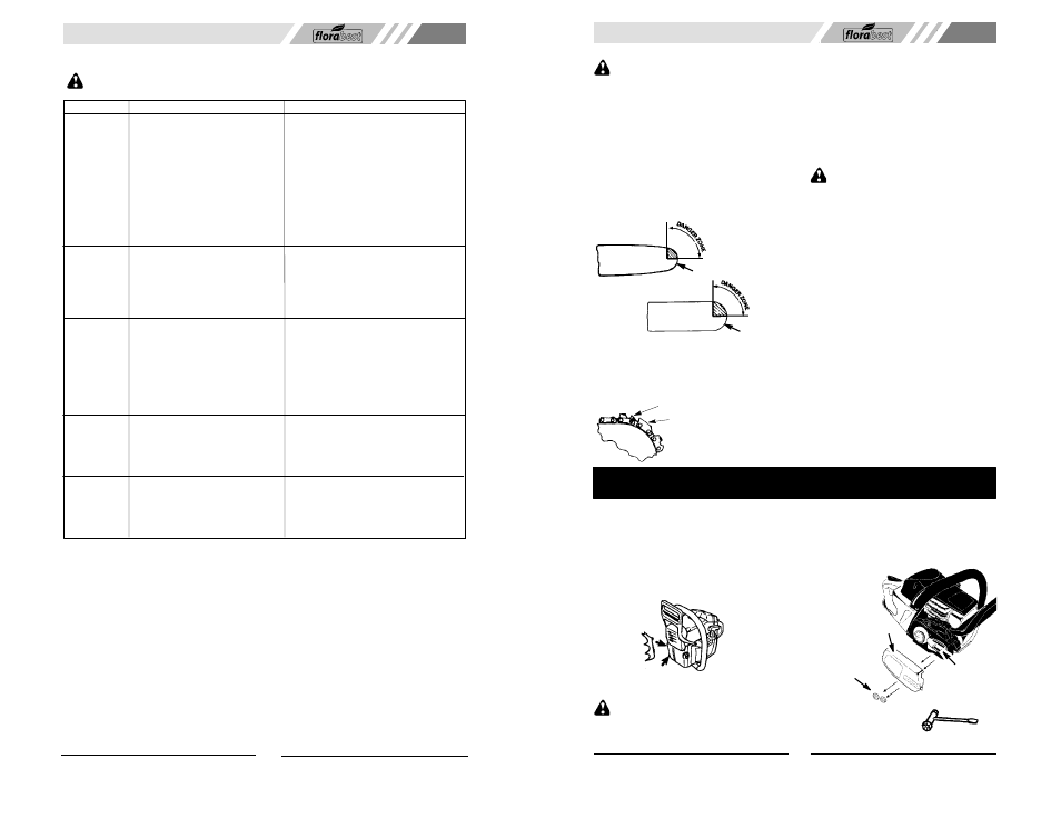
ATTACHING THE BUMPER SPIKE
The bumper spike may be used as a pivot
when making a cut.
1. Loosen and remove the bar nuts and the
clutch cover from the saw.
2. Attach the bumper spike with the two
screws as illustrated.
ATTACHING THE BAR & CHAIN
(If not already attached)
WARNING
: Recheck each assem-
bly step if the saw is received assembled. Al-
ways wear gloves when handling the chain.
The chain is sharp and can cut you even
when it is not moving!
1. Loosen and remove the bar nuts and the
clutch cover from the saw.
2. Remove the plastic shipping spacer (if
present).
Clutch cover
Bar nuts
Chain adjustment tool
(Bar Tool)
Location of
shipping
spacer