Location of memory modules, Flash dimm replacement procedure – Enterasys Networks Enterasys Matrix 9034310-01 User Manual
Page 51
Memory Locations and Replacement Procedures
Matrix DFE-Platinum Series Hardware Installation Guide B-3
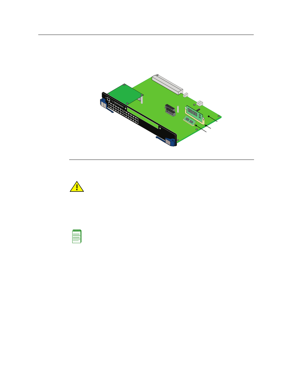
Location of Memory Modules
shows the locations of the DRAM SIMM and DIMM on the main board of the
2G4082‐25.
Figure B-2 Memory Module Locations on the 2G4082-25
Flash DIMM Replacement Procedure
Removing the DIMM from 2G4082-25
To remove the DIMM from the 2G4082‐25, proceed as follows:
1.
If an optional network expansion module (NEM) is installed on the main board of the
2G4082‐25, refer to
on page B‐4 and proceed to step 1a. Otherwise proceed to
step 2.
a.
Remove and save the three screws attaching the NEM to the front panel and to the
standoff on the main PC board.
b. Lift the NEM straight up and off the two module connectors on the main PC board.
1
Flash DIMM
2 DRAM SIMM
3 Main PC board
COM
OFFLINE/ RESET
MGMT
CPU
1
2
GR
OUP
SELECT
1X
11X
13X
12X
14X
23X
24X
G R
O U
P
1
G R
O U
P
2
GR
OUP
1
2
3
4
5
6
7
8
9
10
11
12
2G
40
82
-2
5
Gb ENET
DFE
А
В
Б
Caution: Observe all Electrostatic Discharge (ESD) precautions when handling sensitive electronic
equipment.
Precaución: Al trabajar con equipos electrónicos sensibles, tome todas las precauciones de
seguridad para evitar descargas de electricidad estática.
Note: Prior to removing the DIMM from a 2G4082-25, you must remove the
NEM
to gain access to
the DIMM memory and connector.