Figure 3‐4, Figure 3‐5 – Enterasys Networks Enterasys Matrix 9034310-01 User Manual
Page 32
Connecting to the Network
3-8 Installation
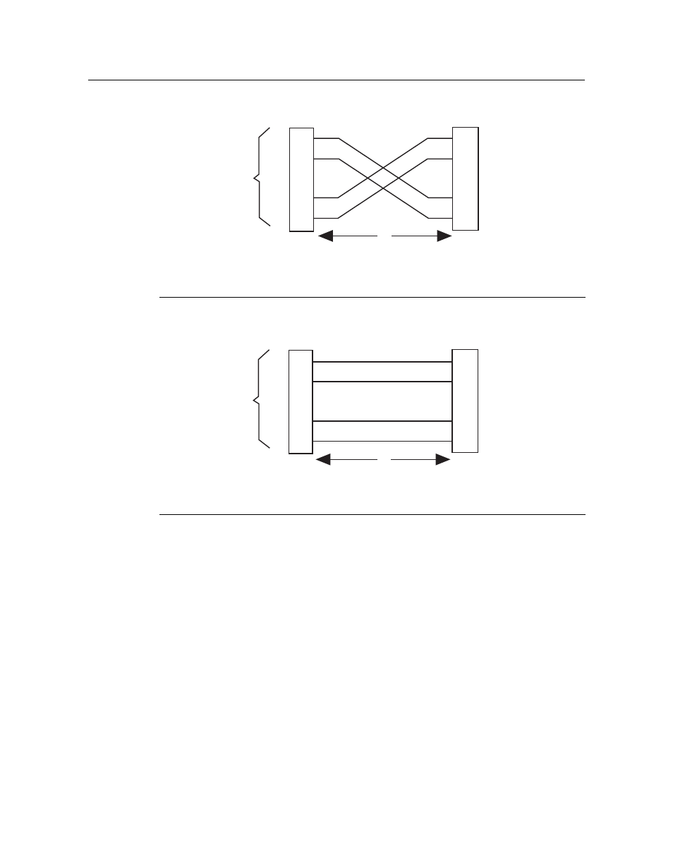
Figure 3-4 Four-Wire Crossover Cable RJ45 Pinouts, Connections Between Hub Devices
Figure 3-5 Four-Wire Straight-Through Cable RJ45 Pinouts, Connections Between
Switches and End User Devices
1 RJ45 device port
3 RJ45-to-RJ45 crossover cable
2 Other device port
4 RX+/RX- and TX+/TX- connections. These connections must
share a common color pair.
1 RJ45 device port
3 RJ45-to-RJ45 straight-through cable
2 Other device port
4 RX+/RX- and TX+/TX- connections. These connections must
share a common color pair.
TX+
TX
RX+
RX 2
1
3
6
TX+
TX
2
1
3
6
RX+
RX
А
Б
В
Г
TX+
TX
RX+
RX 2
1
3
6
TX+
TX
2
1
3
6
RX+
RX
А
Б
В
Г
This manual is related to the following products: