Adapter wiring and signal assignments, Adapter wiring and signal assignments -13, Connecting to a modem -13 – Enterasys Networks Enterasys Matrix 9034310-01 User Manual
Page 37: Дв г а е, Figure 3-10 connecting to a modem
Pin Out Descriptions
Connecting to COM Port for Local Management
Matrix DFE-Platinum Series Installation Guide 3-13
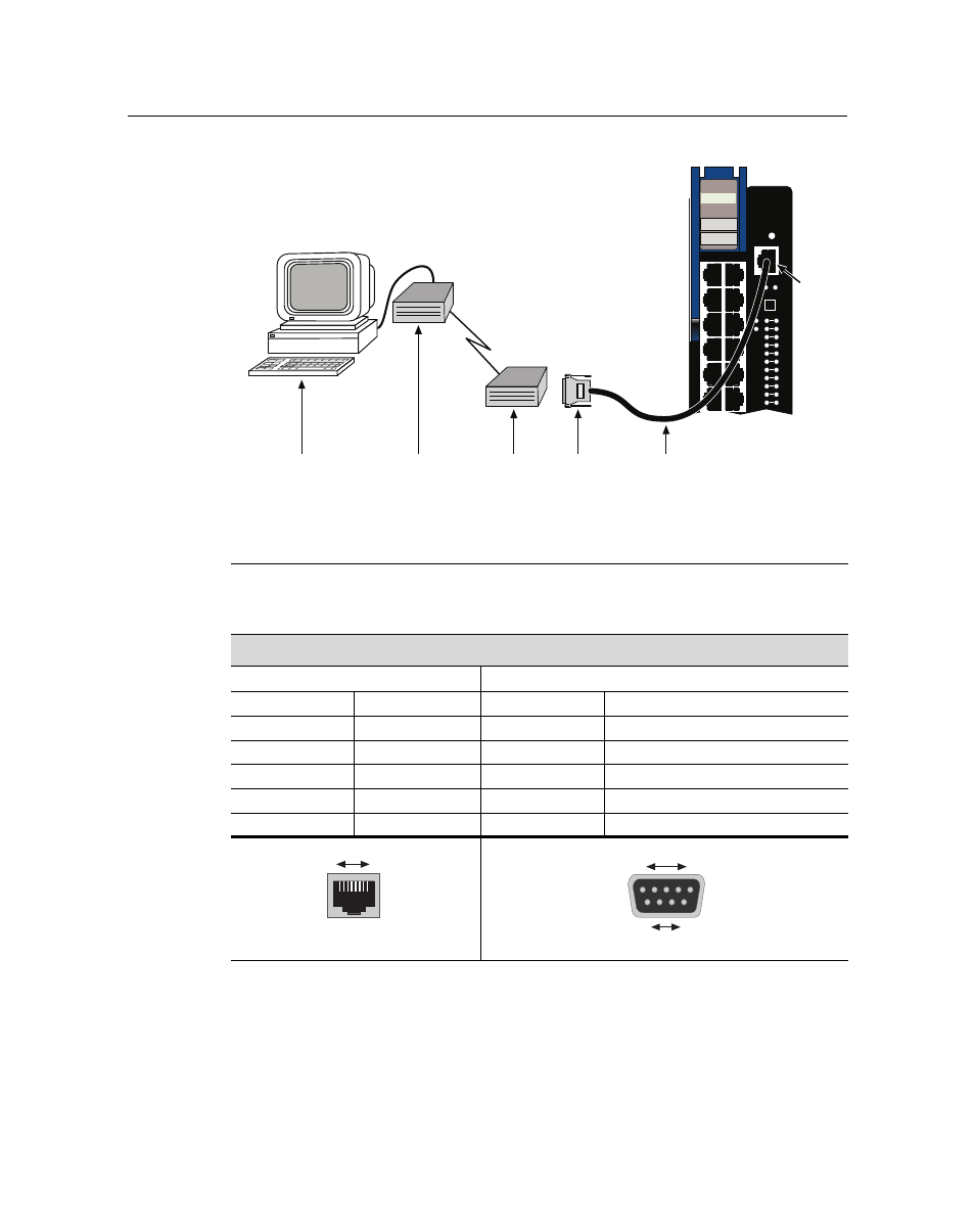
Figure 3-10 Connecting to a Modem
Adapter Wiring and Signal Assignments
1 UTP straight-through cable with RJ45 connectors
4 Local modem
2 RJ45 COM port
5 Remote modem
3 RJ45-to-DB25 modem adapter
6 Remote PC
Д
В
Г
А
Е
2G4082-25
Gb ENET
COM
OFFLINE/
RESET
MGMT
CPU
1
2
GROUP
SELECT
1X
11X
12X
G
R
O
U
P
1
GROUP
1
2
3
4
5
6
7
8
9
10
11
12
Á
COM Port Adapter Wiring and Signal Diagram
RJ45
DB9
Pin
Conductor
Pin
Signal
1
Blue
2
Receive (RX)
4
Red
3
Transmit (TX)
5
Green
5
Ground (GRD)
2
Orange
7
Request to Send (RTS)
6
Yellow
8
Clear to Send (CTS)
RJ45 Connector (Female)
8
1
Pins
DB9 Connector (Female)
Pins
1
5
6
9
This manual is related to the following products: