Figure 3‐6, Figure 3‐7 – Enterasys Networks Enterasys Matrix 9034310-01 User Manual
Page 33
Connecting to the Network
Matrix DFE-Platinum Series Installation Guide 3-9
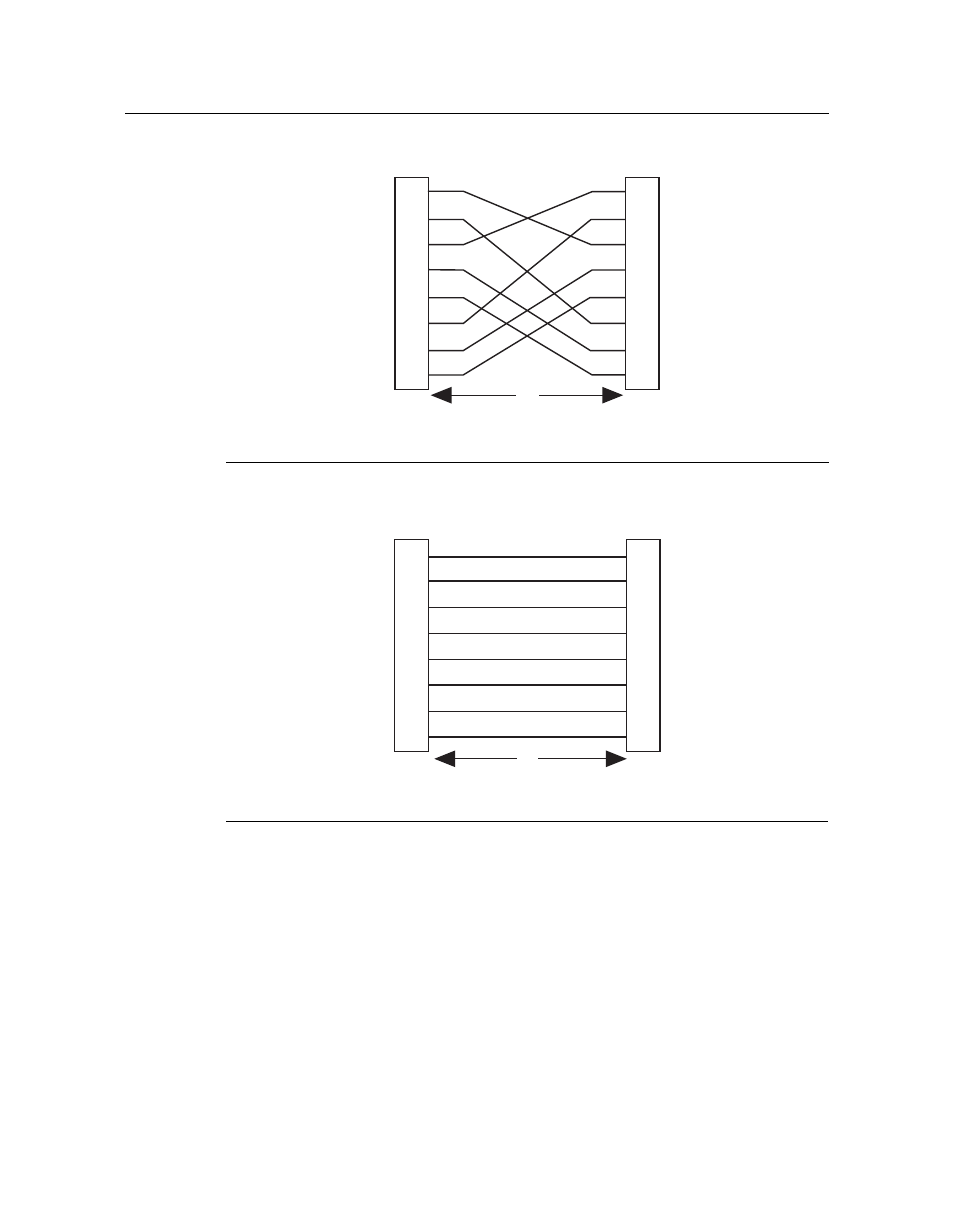
Figure 3-6 Eight-Wire Crossover Cable RJ45 Pinouts, Connections Between Hub Devices
Figure 3-7 Eight-Wire Straight-Through Cable RJ45 Pinouts, Connections Between
Switches and End-User Devices
e.
Ensure that the twisted pair connection meets the dB loss and cable specifications outlined
in the Cabling Guide. Refer to “
” on page xii for information on
obtaining this document. If a link is still not established, contact Enterasys Networks.
Refer to “
” on page xiii for details.
4.
Repeat steps 1 through 3 above, until all connections have been made.
1 RJ45 device port
3 RJ45-to-RJ45 crossover cable
2 Other device port
1 RJ45 device port
3 RJ45-to-RJ45 straight-through cable
2 Other device port
2
1
3
6
4
5
7
8
TX1+
TX2+
RX4-
RX1-
TX4+
RX3-
TX3+
RX2-
TX2+
TX1+
RX3-
RX2-
TX3+
RX4-
TX4+
RX1-
2
1
3
6
4
5
7
8
Б
А
В
TX1+
TX2+
RX4-
RX1-
TX4+
RX3-
TX3+
RX2-
2
1
3
6
4
5
7
8
TX2+
TX1+
RX3-
RX2-
TX3+
RX4-
TX4+
RX1-
2
1
3
6
4
5
7
8
А
В
Б