Pclink transmission format – Yaskawa MP2000 Series User Manual
Page 27
Page 27
MP2000.02, 1/18/2011
Data subject to change without notice
Yaskawa America, Inc.
4. PCLINK Transmission Format
4.1 Link Transmission
The link transmission function communicates data cyclically between the devices connected by PCLINK simply by
performing link assignment with an engineering tool. No ladder program is necessary to send and receive data. An
outline of the function is given below.
4.1.1 Link
Data
Assignment
• Register
Maximum:
2048
words
•
Coil Maximum: 2048 bits
• Per-station
Output
Size
Conditions
Coil Output (16-point units) + Register Output 256 words
•
Link Size Restrictions in the PCLINK Network
Because the data size that can be used differs between the MP series and the GL120/130 series PCLINK
(registers: 2048 words, coils: 2048 bits) and the GL40, 60 and 70 series PCLINK (registers: 1024 words, coils:
1024 bits), when they are combined on the same network it is necessary to compose the system with small upper
limit on size with 1024 words for registers, and 1024 bits for coils.
•
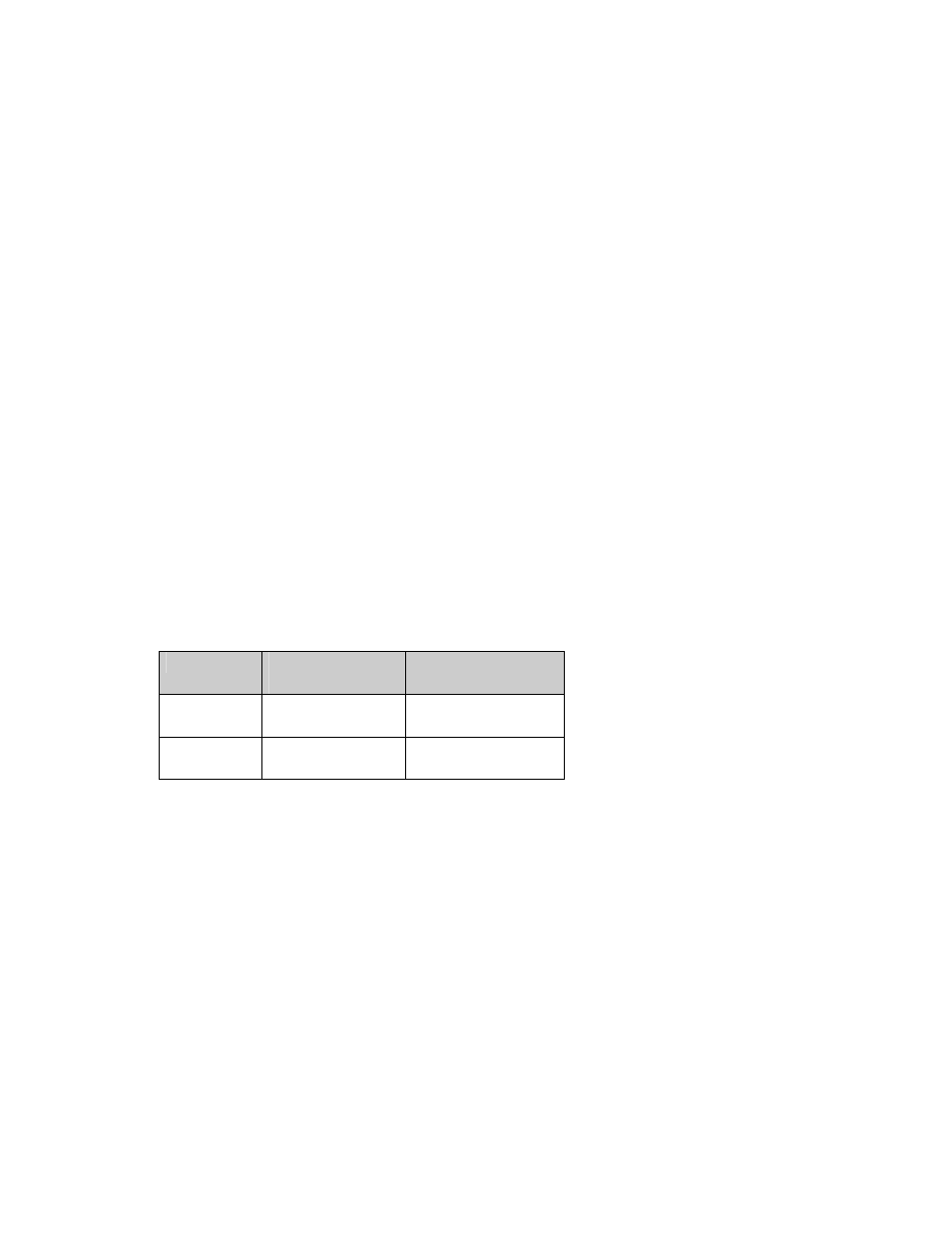
Link Coils and Link Registers
In GL series PCLINK, the registers used in PCLINK transmission use dedicated registers for link coils (Dxxxx) and
for link registers (Rxxxx). Because there are no dedicated registers in the MP series PCLINK modules, I/O
registers (OB, IB in the case of link coil access, and OW, IW for link register access) are used instead. The
following shows the correspondence between the link coil, link registers and I/O registers (an I/O register number
for example).
Type
GL120/130
Reference Number
MP PCLINK
Reference Number
Register Ru0001~Ru2048
IW0000~IW07FF
OW0000~OW07FF
Coil Du0001~Du2048
IB08000~IB087FF
OB08000~OB087FF
u: Channel number 1 or 2
*The I/O register lead number and end number are indicated when the PCLINK-01 module is assigned in an
MP series controller. In the PCLINK module, an I/O register of a maximum 2176 words (2048 words + 2048 bits)
is needed. (The size can be contracted as needed.)