Communication connector, Ethercat, Option status leds – Yaskawa SI-ES3 for V1000 User Manual
Page 12: 5 ethercat® option components
5 EtherCAT® Option Components
EN 12
YASKAWA Europe YEU TOEP C710606 98A - V1000 Option EtherCAT - Installation Manual
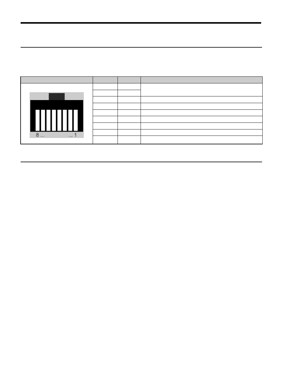
Communication connector
The EtherCAT
®
Option is connected to the network using a RJ45 connector. The pin
assignment is explained in
.
Table E.4 Communication connector (RJ45)
EtherCAT
®
Option Status LEDs
The EtherCAT
®
Option has four LEDs that indicate the communication status. The
indications conform with DS303, Part 3: Indicator Specification.
LEDs L/A OUT and L/A IN: Ethernet Link/Activity 1 and 2
The Link/Activity indicators show the status of the physical link and show activity on the
link period
RUN LED
A green lit EtherCAT
®
RUN LED indicates the status of the EtherCAT
®
network state
machine.
A red lit EtherCAT
®
RUN LED is only used by the NOID firmware loader, refer to
EtherCAT
®
ERROR indicator
The red EtherCAT
®
error LED indicates the presence of any errors.
EtherCAT
®
Connector
Pin
Signal
Description
1
TD+
Send data
2
TD-
3
RD+
Receive data
4
–
N.C. (Pins denoted as N.C. do not connect to any signal)
5
–
N.C. (Pins denoted as N.C. do not connect to any signal)
6
RD-
Receive data
7
–
N.C. (Pins denoted as N.C. do not connect to any signal)
8
–
N.C. (Pins denoted as N.C. do not connect to any signal)
Housing
–
Shield