Yaskawa LEGEND Digital Torque Amplifier User Manual
Page 42
3.2 Rotary Motor Mounting
31
■
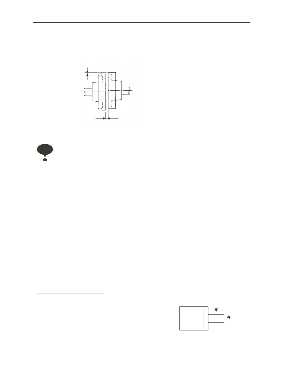
Alignment
Upon mating to the machine, make sure the motor shaft core and the machine shaft core
are coupled in a straight line. Mount the servomotor so that it falls within the alignment
accuracy in the figure below.
(1) Improper alignment can lead to vibration, which risks damaging the shaft coupling.
(2) When mounting the coupling, do not apply shock directly to the shaft. This may damage the encoder mounted
on the shaft end opposite the load.
■
Mounting Direction
The SGM□H servomotor can be mounted in either the horizontal or vertical directions.
■
Shaft Tolerance Ranges
Design machine systems so that the thrust loads and radial loads
1
applied to the
servomotor shaft during operation fall within the tolerances in Table 3.1.
The allowable radial loads shown in the table are the maximum loads that can be applied
to the end of the output shaft.
1. Thrust Load, Radial Load:
Thrust Load (Fs): The shaft load applied parrallel to the shaft core.
Radial Load (Fr): Shaft load applied at a right angle to the shaft core.
The maximum deviation at all four sides cannot
exceed 0.03mm (rotated with the coupling)
The maximum deviation at all four sides cannot
exceed 0.03mm (rotated with the coupling)
Important
Fr
Fs
Shaft
Motor