4 cable specifications and peripheral devices, Wiring precautions, Cable specifications – Yaskawa LEGEND Digital Torque Amplifier User Manual
Page 35: Caution
2.4 Cable Specifications and Peripheral Devices
24
2.4 Cable Specifications and Peripheral Devices
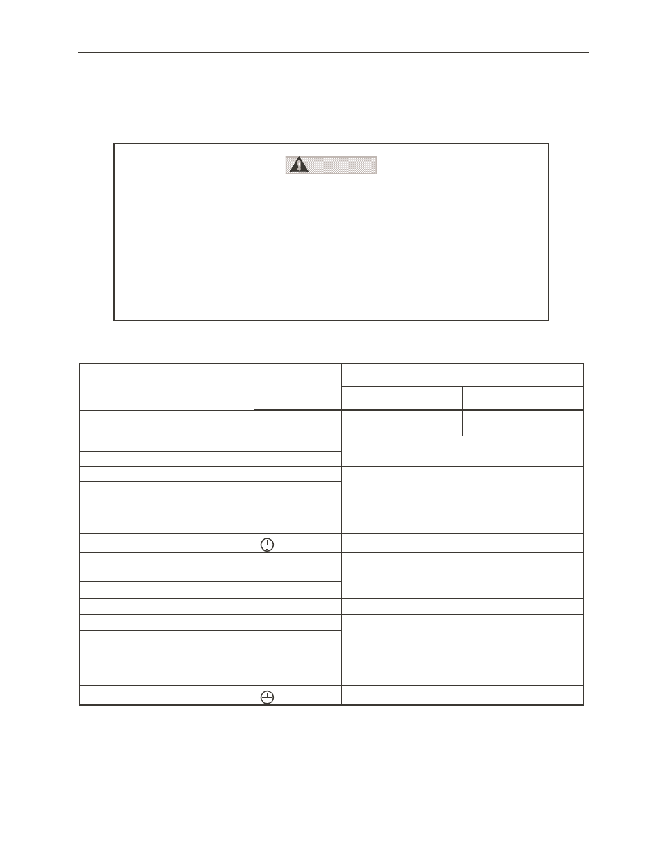
Ratings and specifications for peripheral devices, as well as cable specifications for digital
torque amplifiers are summarized in the tables below.
■
Cable Specifications
Notes:
1.
Wire sizes were selected for three cables per bundle at 40°C ambient temperature with the rated current.
2.
Use cables with a minimum withstand voltage of 600V for main circuits.
3.
If cables are bundled in PVC or metal ducts, consider the reduction ratio of the allowable current.
4.
Use heat-resistant cable under high ambient or panel temperatures where normal vinyl cable will rapidly
deteriorate.
External Terminal Name
SGDG
Terminal
Symbol
Wire Size AWG [in
2
(mm
2
)]
01GT
04GT
Main circuit power input terminals
L1, L2
(Single Phase)
16 AWG [HIV 0.002
(1.25)]
14 AWG [0.003 (2.0)]
Servomotor connection terminals
U, V, W
16 AWG [HIV 0.002 (1.25)]
Control power supply terminals
L1C, L2C
Control I\O signal connector
CN1
Twisted pair or shielded twisted pair wires
Core wire at least 28 AWG [0.0002
(0.12)], tinned,
annealed copper twisted wires
Finished cable dimensions:
maximum
Φ
0.63in (16mm) for CN1 and
Φ
0.27in
(6.8mm) for CN2.
PG signal connector
CN2
Ground terminal
14 AWG [HIV 0.003 (2.0)]
Main circuit power input terminals
L1, L2, L3
(Three-phase)
14 AWG [HIV 0.003 (2.0)]
Servomotor connection terminals
U, V, W
Control power supply terminals
L1C, L2C
16 AWG [HIV 0.002 (1.25)]
Control I\O signal connector
CN1
Twisted pair or shielded twisted pair wires
Core wire at least 28 AWG [0.0002
(0.12)], tinned,
annealed copper twisted wires
Finished cable dimensions: maximum
Φ0.63in
(16mm) for CN1 and
Φ0.27in (6.8mm) for CN2.
PG signal connector
CN2
Ground terminal
14 AWG [HIV 0.003 (2.0)]
Wiring Precautions
•
Do not bundle or run power and signal lines together in the same duct.
Keep power and signal lines at least 11.81” (30cm) apart.
•
Use twisted pair or shielded multi-core twisted pair wires for signal and
encoder (PG) feedback lines.
•
The maximum lengths for signal lines are as follows:
•
Maximum of 9.84ft (300cm) for reference input lines.
•
Maximum of 65.6ft (20m) for PG feedback lines.
•
Use a cable with 164 ft (50m) specifications for distances over 65.6ft (20m).
CAUTION