Output circuits and interfaces – Yaskawa LEGEND Digital Torque Amplifier User Manual
Page 32
2.2 Input Signals
21
■
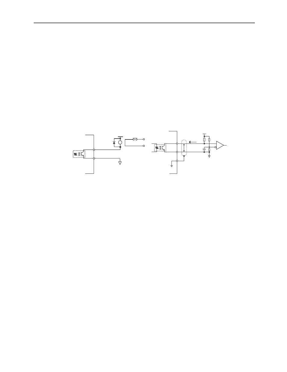
Output Circuits and Interfaces
The output signal circuits of the digital torque amplifier are of the three types shown
below. Configure the input circuit on the upper-level device to match each of these output
circuits.
• Connection with Line Driver Output Circuits
The output signals (PAO, *PAO, PBO, *PBO) where the encoder serial data was
converter to a 2-phase (A-phase, B-phase) pulse, and the origin pulse signal (PCO,
*PCO) are output by the line driver circuit. The upper-level device receives these
through the line receiver circuit. See “
2.3 Wiring to the Encoder
” for an example of
the connection circuit.
• Connection with Photocoupler Output Circuit
Servo alarms and other output signals for sequence use are configured in the
photocoupler output circuit. They are connected through the relay and line driver
circuits.
Note: The maximum allowable voltage and current capacity of the photocoupler output circuit are as
follows:
• Voltage: DC30V(Max.)
• Current: DC50mA(Max.)
0V
DC5V
~
24V
Digital Torque
Amplifier Side
Relay
0V
P
Digital Torque
Amplifier Side
DC5V
~
12V
- Tag Generator (30 pages)
- MP3300iec (82 pages)
- 1000 Hz High Frequency (18 pages)
- 1000 Series (7 pages)
- PS-A10LB (39 pages)
- iQpump Micro User Manual (300 pages)
- 1000 Series Drive Option - Digital Input (30 pages)
- 1000 Series Drive Option - CANopen (39 pages)
- 1000 Series Drive Option - Analog Monitor (27 pages)
- 1000 Series Drive Option - CANopen Technical Manual (37 pages)
- 1000 Series Drive Option - CC-Link (38 pages)
- 1000 Series Drive Option - CC-Link Technical Manual (36 pages)
- 1000 Series Drive Option - DeviceNet (37 pages)
- 1000 Series Drive Option - DeviceNet Technical Manual (81 pages)
- 1000 Series Drive Option - MECHATROLINK-II (32 pages)
- 1000 Series Drive Option - Digital Output (31 pages)
- 1000 Series Drive Option - MECHATROLINK-II Technical Manual (41 pages)
- 1000 Series Drive Option - Profibus-DP (35 pages)
- AC Drive 1000-Series Option PG-RT3 Motor (36 pages)
- Z1000U HVAC MATRIX Drive Quick Start (378 pages)
- 1000 Series Operator Mounting Kit NEMA Type 4X (20 pages)
- 1000 Series Drive Option - Profibus-DP Technical Manual (44 pages)
- CopyUnitManager (38 pages)
- 1000 Series Option - JVOP-182 Remote LED (58 pages)
- 1000 Series Option - PG-X3 Line Driver (31 pages)
- SI-EN3 Technical Manual (68 pages)
- JVOP-181 (22 pages)
- JVOP-181 USB Copy Unit (2 pages)
- SI-EN3 (54 pages)
- SI-ET3 (49 pages)
- MECHATROLINK-III (35 pages)
- EtherNet/IP (50 pages)
- SI-EM3 (51 pages)
- 1000-Series Option PG-E3 Motor Encoder Feedback (33 pages)
- 1000-Series Option SI-EP3 PROFINET (56 pages)
- PROFINET (62 pages)
- AC Drive 1000-Series Option PG-RT3 Motor (45 pages)
- SI-EP3 PROFINET Technical Manual (53 pages)
- A1000 Drive Option - BACnet MS/TP (48 pages)
- 120 Series I/O Modules (308 pages)
- A1000 12-Pulse (92 pages)
- A1000 Drive Software Technical Manual (16 pages)
- A1000 Quick Start (2 pages)
- JUNMA Series AC SERVOMOTOR (1 page)
- A1000 Option DI-101 120 Vac Digital Input Option (24 pages)