Fig. 3 – Yaskawa V7N Drive with DeviceNet User Manual
Page 35
Section 11
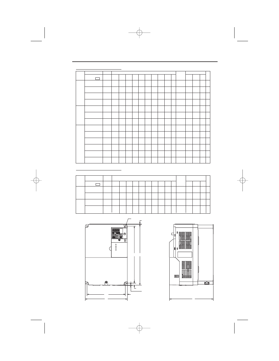
Drive Dimensions
Model
Size
Dimensions in inches (mm)
Weight
Heat Loss (W)
Voltage
CIMR-
Heat-
Internal Total
Class
V7NU
HP
W
H
D
W1
H1
H2
W2
H3
H4
d
(kg)
sink
Fig.
20P1
1/8
2.68
5.83
3.58
2.20
4.65
0.20
0.24
5.04
0.79
M4
1.55
3.7
9.3
13.0
1
(68)
(148)
(91)
(56)
(118)
(5)
(6)
(128) (20)
(0.7)
20P2
1/4
2.68
5.83
3.58
2.20
4.65
0.20
0.24
5.04
0.79
M4
1.55
7.7
10.3
18.0
1
230V
(68)
(148)
(91)
(56)
(118)
(5)
(6)
(128) (20)
(0.7)
3-phase
20P4
1/2
2.68
5.83
4.84
2.20
4.65
0.20
0.24
5.04
0.79
M4
2.20
15.8
12.3
28.1
1
(68)
(148) (123)
(56)
(118)
(5)
(6)
(128) (20)
(1.0)
20P7
3/4 & 1
2.68
5.83
5.63
2.20
4.65
0.20
0.24
5.04
0.79
M4
2.65
28.4
16.7
45.1
1
(68)
(148) (143)
(56)
(118)
(5)
(6)
(128) (20)
(1.2)
21P5
2
4.25
5.83
5.75
3.78
4.65
0.20
0.24
5.04
0.79
M4
3.53
53.7
19.1
72.8
2
(108)
(148)
(146)
(96)
(118)
(5)
(6)
(128)
(20)
(1.6)
230V
22P2
3
4.25
5.83
6.10
3.78
4.65
0.20
0.24
5.04
0.79
M4
3.75
60.4
34.4
94.8
2
3-phase
(108)
(148)
(155)
(96)
(118)
(5)
(6)
(128)
(20)
(1.7)
23P7
5
5.51
5.83
6.22
5.04
4.65
0.20
0.24
5.04
0.79
M4
5.30
96.7
52.4
149.1
2
(140)
(148)
(158) (128) (118)
(5)
(6)
(128)
(20)
(2.4)
40P2
1/2
4.25
5.83
4.21
3.78
4.65
0.20
0.24
5.04
0.79
M4
2.65
9.4
13.7
23.1
2
(108)
(148)
(107)
(96)
(118)
(5)
(6)
(128)
(20)
(1.2)
40P4
3/4
4.25
5.83
4.92
3.78
4.65
0.20
0.24
5.04
0.79
M4
2.65
15.1
15.0
30.1
2
(108)
(148)
(125)
(96)
(118)
(5)
(6)
(128)
(20)
(1.2)
460V
40P7
1 & 2
4.25
5.83
6.10
3.78
4.65
0.20
0.24
5.04
0.79
M4
3.75
30.3
24.6
54.9
2
3-phase
(108)
(148)
(155)
(96)
(118)
(5)
(6)
(128)
(20)
(1.7)
41P5
3
4.25
5.83
6.73
3.78
4.65
0.20
0.24
5.04
0.79
M4
3.75
45.8
29.9
75.7
2
(108)
(148)
(171)
(96)
(118)
(5)
(6)
(128)
(20)
(1.7)
42P2
3
4.25
5.83
6.73
3.78
4.65
0.20
0.24
5.04
0.79
M4
3.75
50.5
32.5
83.0
2
(108)
(148)
(171)
(96)
(118)
(5)
(6)
(128)
(20)
(1.7)
43P7
5
5.51
5.83
6.22
5.04
4.65
0.20
0.24
5.04
0.79
M4
5.30
73.4
44.5
117.9
2
(140)
(148)
(158) (128) (118)
(5)
(6)
(128)
(20)
(2.4)
V7N Enclosed wall mounted type
Model
Size
Dimensions in inches (mm)
Weight
Heat Loss (W)
Voltage
CIMR-
Heat- Internal Total
Class
V7NU
HP
W
H
D
W1
H1
H2
W2
H3
H4
d
(kg)
sink
Fig.
25P5
7.5
7.09
10.24
7.28
6.46
9.61
0.31
0.31
–
–
M5
11.45
170.4
79.4
249.8
3
230V
(180)
(260)
(185) (164) (244)
(8)
(8)
(5.2)
3-phase
27P5
10
7.09
10.24
7.28
6.46
9.61
0.31
0.31
–
–
M5
11.89
219.2
98.9
318.1
3
(180)
(260)
(185) (164) (244)
(8)
(8)
(5.4)
45P5
7.5 & 10
7.09
10.24
7.28
6.46
9.61
0.31
0.31
–
–
M5
10.14
168.8
87.7
256.5
3
460V
(180)
(260)
(185) (164) (244)
(8)
(8)
(4.6)
3-phase
47P5
10
7.09
10.24
7.28
6.46
9.61
0.31
0.31
–
–
M5
10.58
209.6
99.3
308.9
3
(180)
(260)
(185) (164) (244)
(8)
(8)
(4.8)
Drives represented in Fig. 3 can be used as "IP00" type enclosures if the top and bottom covers are removed.
V7N Enclosed wall mounted type
H1
H
4-d
0.06
(1.5)
H2
W
0.09
(2.20)
D
W1
W2
MS
NS
Fig. 3
35
IG.V7N.qxd:IG.V7N.qxd 6/5/07 3:22 AM Page 35