Wiring terminal functions and voltages – Yaskawa V7N Drive with DeviceNet User Manual
Page 11
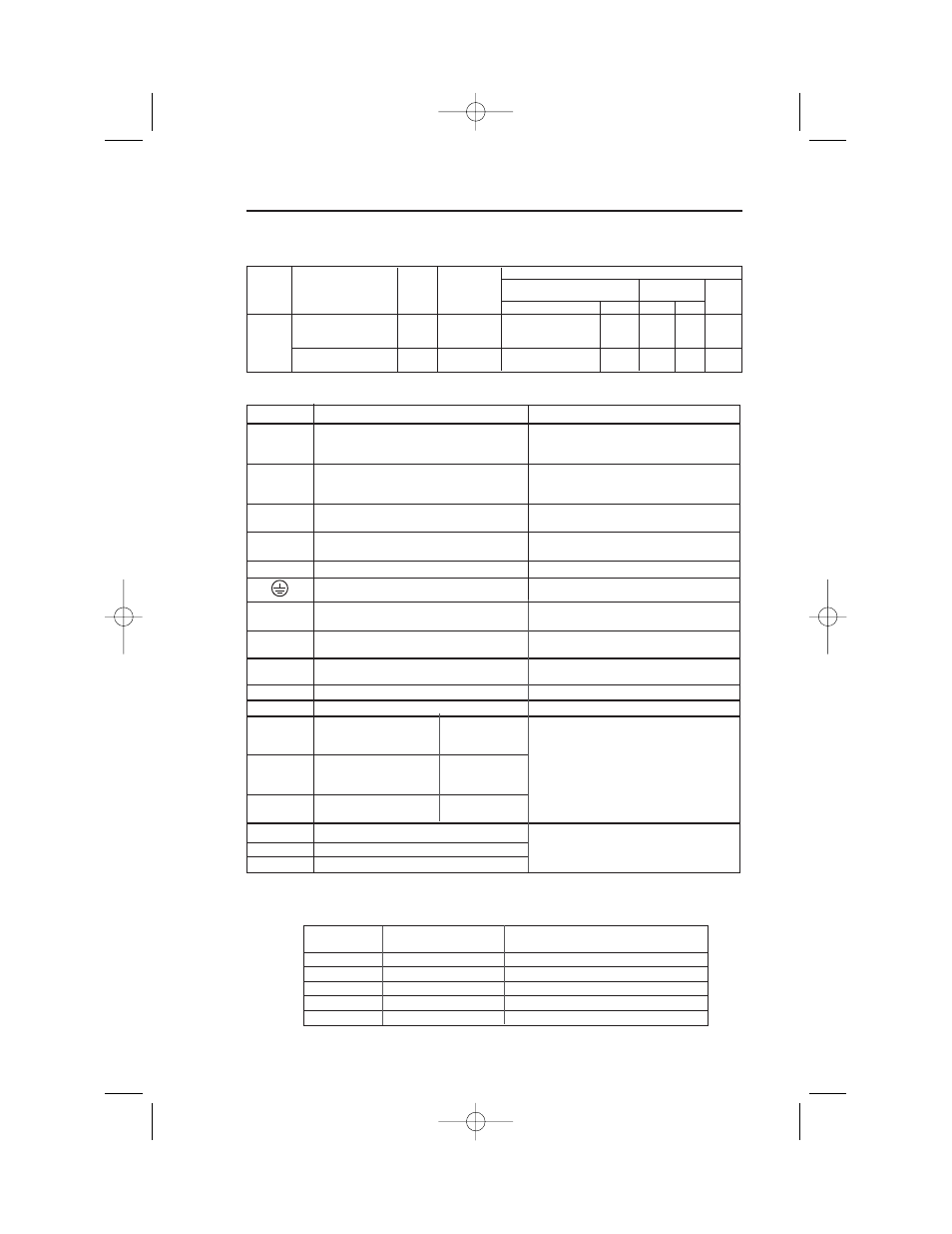
TERMINAL
FUNCTION
VOLTAGE / SIGNAL LEVEL
L1 (R)
230V Drive: 200 / 208 / 220 / 230V at 50/60 Hz
L2 (S)
Main circuit input power supply
460V Drive: 380 / 400 / 440 / 460 / 480V
L3 (T)
at 50/60 Hz
T1 (U)
T2 (V)
Main circuit output
230V Drive: 0 - 200 / 208 / 220 / 230V
T3 (W)
460V Drive: 0 - 400 / 440 / 460 / 480V
B1
For connection of braking resistor (option)
B2
+1
DC Reactor terminals
+2
–
DC Bus terminals (+1 & –)
Ground terminal (100 ohms or less)
– – – –
S1
Multi-Function-Input 1
Factory setting is "
Forward Run/Stop
" (1).
(Forward run when closed, stop when open)
S2
Multi-Function-Input 2
Factory setting is "
Reverse Run/Stop
" (1).
(Reverse Run when closed, stop when open)
S3
Multi-Function-Input 3
Factory setting is "
External Fault (NO contact)
input
" (1)
S4
Multi-Function-Input 4
Factory setting is "
Fault Reset
" (1)
SC
Sequence common for terminals S1-S4.
Common terminal for sequence inputs
P1
Multi-Function Open
Factory setting is
Collector Output 1
"
Drive Running
"
Photocoupler output:
P2
Multi-Function Open
Factory setting is
48 VDC; 50 mA or less.
Collector Output 2
"
Speed Agree
"
PC
Multi-Function Open
0 V
Collector Output common
CN2 V
Frequency reference voltage input
0 to +10 / 100% (20K )
CN2 I
Frequency reference current input
4 to 20 mA (250 )
CN2 C
Frequency reference input common
0V
Section 4
Tightening
Wire
Model
Terminal Symbol
Screw
Torque
Applicable size
Recommended
lb • in (N • m)
size
Type
mm
2
AWG
mm
2
AWG
1.94 to 2.21
twisted wire 0.5 to 0.75 20 to 18
Shielded
S1 to S4, P1, P2, SC, PC
M2
(0.22 to 0.25) single
0.5 to 1.25 20 to 16
0.75
18
wire or
equivalent
4.44 to 5.33
Thin
DeviceNet
DeviceNet Connector
M3
(0.5 to 0.6)
twisted wire 0.2 to 2.5
24 to 12
0.32/.2 22/24
Cable
Table 1-1. Wire and Terminal Screw Sizes - continued
Common
to
all models
Table 1-2. Terminal Functions and Voltages
NOTES:
1.
These inputs have factory settings based on 2-wire reset. For 3-wire reset definitions, see Figure 1-6.
TERMINAL
NAME
FUNCTION
BLACK
V-
DeviceNet power supply ground
BLUE
CAN_L
DeviceNet data low
GREEN
Shield
Shield wire
WHITE
CAN_H
DeviceNet data high
RED
V+
DeviceNet power supply +24VDC
Table 1-3. Terminal Functions and Signals of DeviceNet
11
Wiring
Terminal Functions and Voltages
IG.V7N.qxd:IG.V7N.qxd 6/5/07 3:22 AM Page 11