Drive parameters – Yaskawa V7N Drive with DeviceNet User Manual
Page 26
26
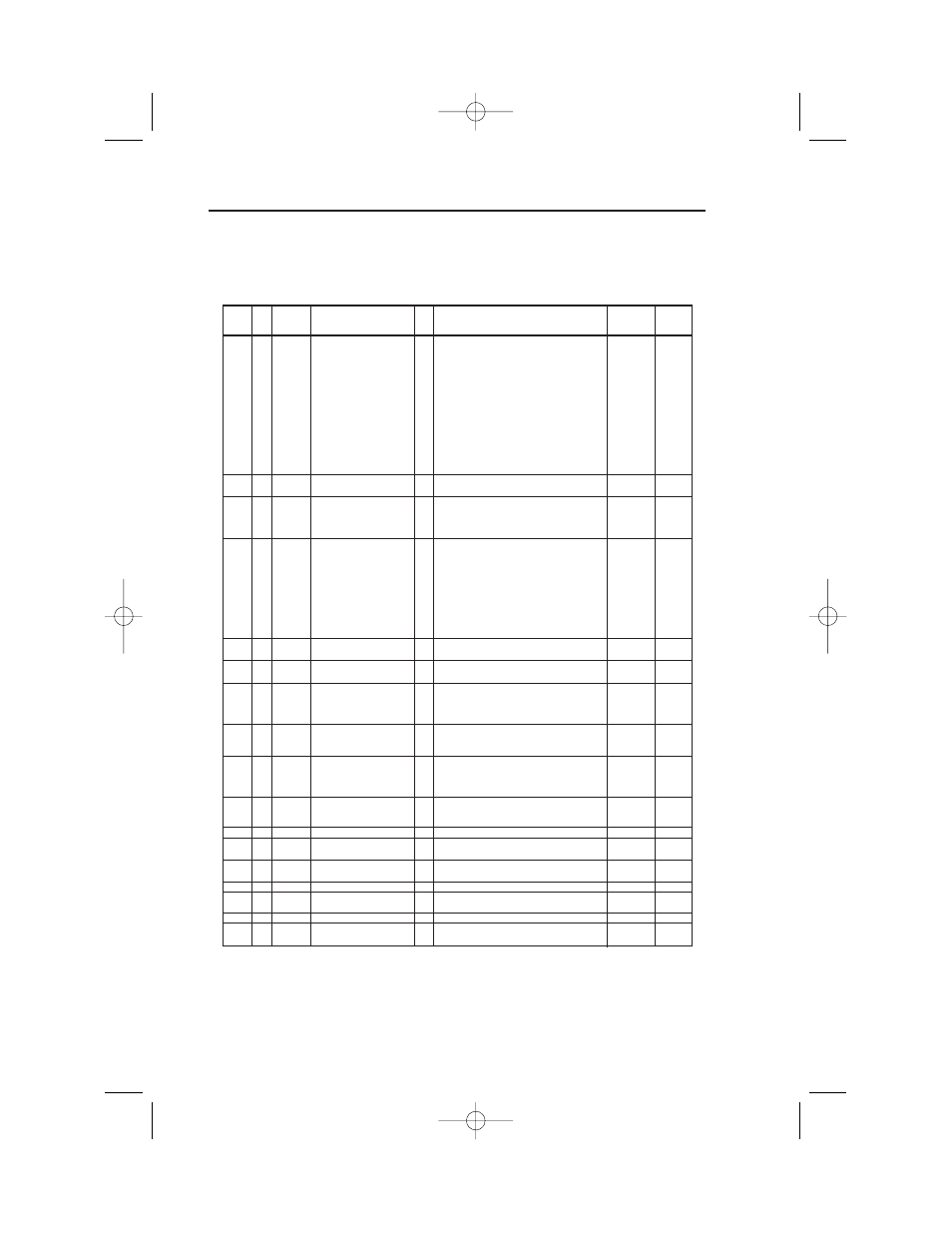
The Drive control circuits use various parameters to select functions and characteristics of the Drive.
Changing of parameter settings must be done in the Program mode, or by use of the Function
LEDs, if available (see TM.V7N.01, Section 4).
Drive Parameters
PARA-
ADDR
CLASS 100
NAME
DATA
SETTING RANGE
SETTING
FACTORY
METER
INST. 01
(AND UNITS)
INCREMENT SETTING
0
0: n001 can be read and set;
n002 - n179 read only
1
1: n001 - n039 can be read and set
2
2: n001 - n079 can be read and set
3
3: n001 - n119 can be read and set
n001 101h
01h
Parameter Selection /
4
4: n001 - n179 can be read and set
Initialization
5
5: n001 - n179 can be read and set
1
1
RUN command accepted during Program mode
6
6: Clear Fault History Only
7
7: Not Used
8
8: 2-wire Initialization (Japan Spec.)
9
9: 3-wire Initialization (Japan Spec.)
10
10:2 wire initialization (USA Spec)
11
11:3 wire initialization (USA Spec.)
n002 102h
02h
Control Method Selection
0
0: V/f Control
1
0
1
1: Open Loop Vector
0
0: Digital Operator
n003 103h
03h
Operation Method Selection
1
1: Terminal
1
3
2
2: Not Used
3
3: DeviceNet
0
0: Digital Operator Pot
1
1: Frequency Reference 1 (n024)
2
2: Not Used
3
3: Not Used
n004 104h
04h
Reference Selection
4
4: Not Used
5
5: Not Used
1
9
6
6: Not Used
7
7: Multi-Function Analog Input (0 to 10V) (CN2)
8
8: Multi-Function Analog Input (4 to 20 mA) (CN2)
9
9: DeviceNet
n005 105h
05h
Stop Method
0
0: Ramp to stop
1
0
1
1: Coast to stop
n006 106h
06h
Reverse Prohibit
0
0: Reverse Run enabled
1
0
1
1: Reverse Run disabled
0
0: STOP key is effective regardless of
programming of n003
n007 107h
07h
STOP Key Function
1
1: STOP key is effective only when sequence
1
0
command (per n003) is from Digital Operator
0
0: Frequency Reference from digital
n008 108h
08h
Reference Selection -
operator pot
1
0
Digital Operator
1
1: Frequency Reference from n024
0
0: ENTER key must be pressed to write-in
n009 109h
09h
Frequency Reference Setting
new value
1
0
Method From Digital Operator
1
1: ENTER key does not have to be pressed
to write-in new value
Operation Selection
0
0: Disabled (operation continues)
n010 10Ah
0Ah
When Digital Operator is
1
1: Enabled (motor coasts to a stop and fault
1
0
Disconnected
is displayed)
n011 10Bh
0Bh
Frequency - Max.
-
50.0 to 400.0
0.1 (Hz)
60.0
n012 10Ch
0Ch
Voltage - Max.
-
0.1 to 255.0 (230V Drive)
0.1 (V)
230.0
0.2 to 510.0 (460V Drive)
460.0
n013 10Dh
0Dh
Frequency - Max.
-
0.2 to 400.0
0.1 (Hz)
60.0
Voltage Point
n014 10Eh
0Eh
Frequency - Midpoint
-
0.1 to 399.9
0.1 (Hz)
(Note 2)
n015 10Fh
0Fh
Voltage - Midpoint
-
0.1 to 255.0 (230V Drive)
0.1 (V)
(Note 2)
0.2 to 510.0 (460V Drive)
n016 110h
10h
Frequency - Min.
-
0.1 to 10.0
0.1 (Hz)
(Note 2)
n017 111h
11h
Voltage - Min.
-
0.1 to 50.0 (230V Drive)
0.1 (V)
(Note 2)
0.2 to 100.0 (460V Drive)
Section 9
Drive Parameter Listing
(n001-n017)
IG.V7N.qxd:IG.V7N.qxd 6/5/07 3:22 AM Page 26